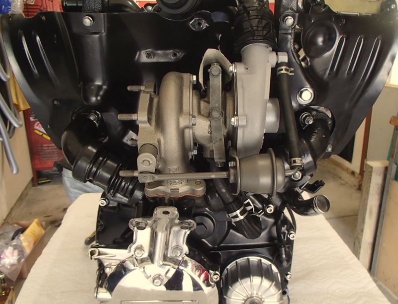
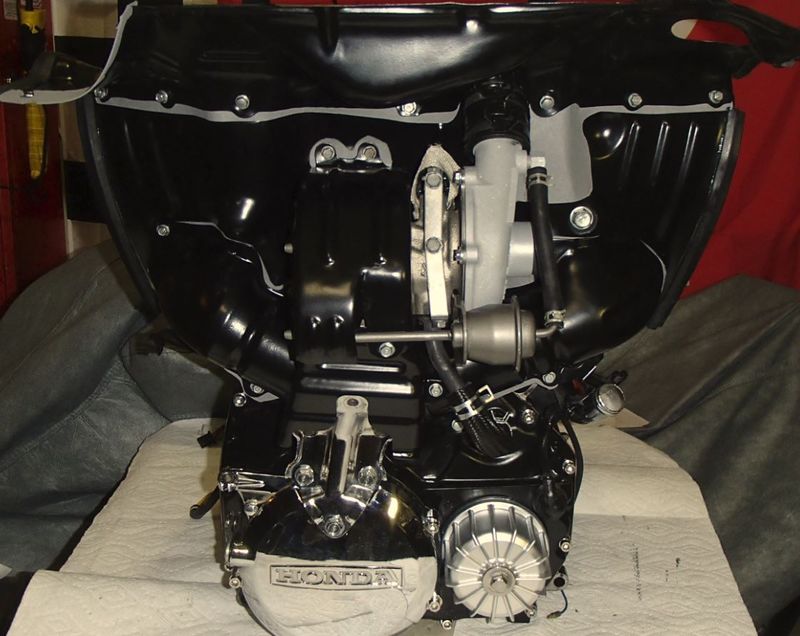
Turbocharger
Welcome to the most interesting part of these machines - the turbocharger itself. Honda was ahead of the pack in releasing the 1982 CX500T and in doing so, was limited to the technology available at the time. Intercoolers were not used on these early designs. No water injection systems were used. No knock sensors or feedback fuel systems were used. This left no mechanism for the early ECUs to know just what was going on inside the engine. If the operator used low octane fuel - it could be a bad day for the pistons. Honda decided to use low compression as its protection. The CX500 T was rated at 7.2 to 1 compression, and 18 psi boost. This left the small displacement heavy bike with a V twin engine resulting in very little torque until boost arrived. This is what was often perceived as "turbo lag". The press was quite verbal on this topic resulting in the 1983 CX 650 turbo with actually 673 ccs, and 9 to 1 compression ration - albeit with only 16 psi boost. The added displacement and compression removed most of the perceived lag, and the Honda name was once again sung far and wide as the leader in technology - sort of.
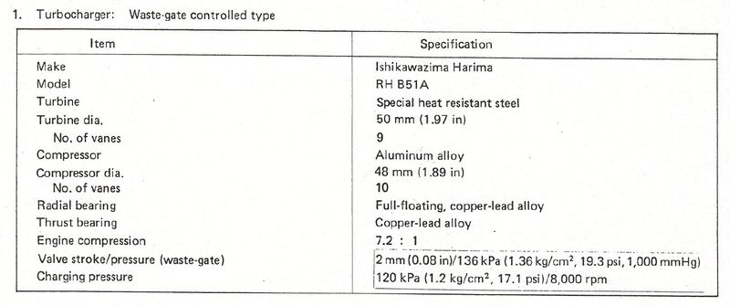
Lets talk about the turbocharger itself. It was manufactured by IHI. IHI has developed turbo units for many Japanese applications, but the CX500 T was the worlds smallest production unit with an impeller wheel of only 50mm diameter. Speed of the turbine could hit 180,000 RPM. A mechanical waste gate would open at just above 17 psi to control boost. If 18 psi or more was detected by the PB sensor, the ECU would turn on the "Fuel System" lamp and put the bike into a limp home mode which was reset upon the next key cycle. This is the typical failure cycle of a stuck waste gate and common problem with these machines after long periods of inactivity. Here are some quick facts from the Honda Fuel Injection Manual.
Diagnosis
How do I know if my turbo is bad?
There are several obvious clues to turbocharger failure. The first is usually noise from the bearings. This will be a high pitched sound during boost. Soon it will be followed by white smoke out the exhaust. This is oil escaping out the bearings/seal into the exhaust instead of the return back to the engine. In all cases, it will be much worse under boost as now it is pressurized being forced out. Finally, the turbo will seize resulting in a severe drop in performance - and no sound. A normal turbo will have a high frequency pitch as boost builds and the turbine spins to 180k RPM. When this changes - there is a problem. The waste gate getting stuck is the most common issue. Some have been able to free it after using various penetrating fluids and careful manipulation.
The turbine and compressor wheels are not serviceable on these. Parts are NLA. The bearings however are still available and unit can be disassembled and these replaced. At this time, most turbo shops offer services such as ceramic coating which will greatly extend future service issues as these new coatings help prevent waste gate sticking as well as insulate the housing providing less heat escape and therefore a slight improvement in the form of less lag. The largest benefit in having a professional shop do this work is in their ability to high speed balance your turbo. This will increase turbo life and provide a smoother boost transition. Costs for a complete rebuild, coating and balance is around $400 USD plus your shipping. This vendor has had a very good reputataion with these turbos and is recommended- Gpopshop
Removal
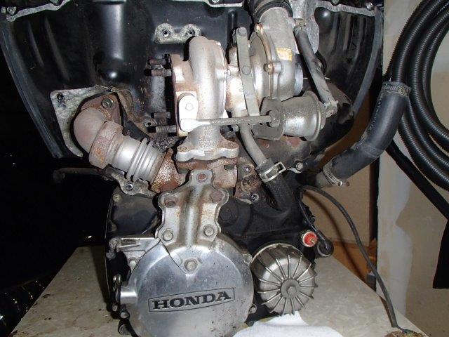
Removal of the turbocharger can be done with the engine in the frame. Its is fairly straight forward. Use the FSM which will step by step give you the proper sequence. No need to reproduce that here. The turbo will be removed as an assembly with the exhaust manifold. Once removed, it can then be separated. Here are some reference photos with comments.
Use a good penetrating fluid such as PB Blaster Available on Ebay to soak all of the exhaust and turbo fasteners. Give it hours and reapply often before attempting to undo these. Broken bolts are not fun. Use a good anti seize going back together. Available on Ebay
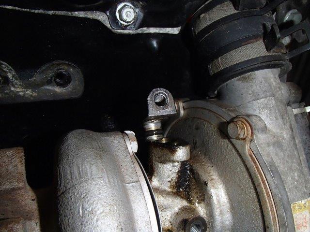
This is a very sensitive part -Be careful! After removing the bolt, gently work the oil feed housing vertically. These are prone to breaking during this phase.
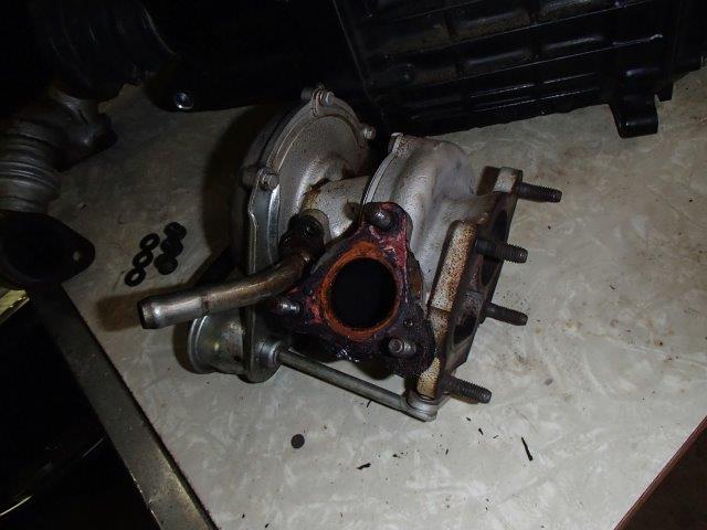
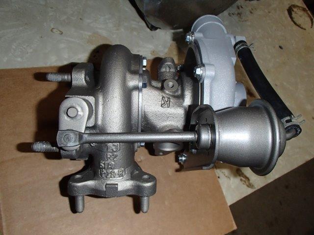
Turbo ready for overhaul.
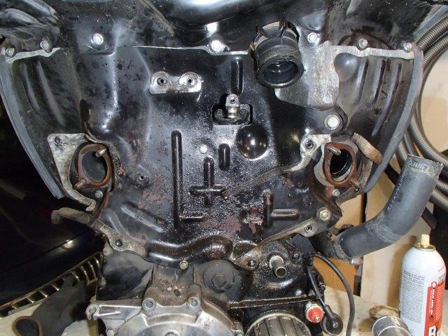
Note the mix of oil and rust. The oil is from a leaking turbo oil feed hose. Ceramic coating the shield is a great solution.
Reassembly
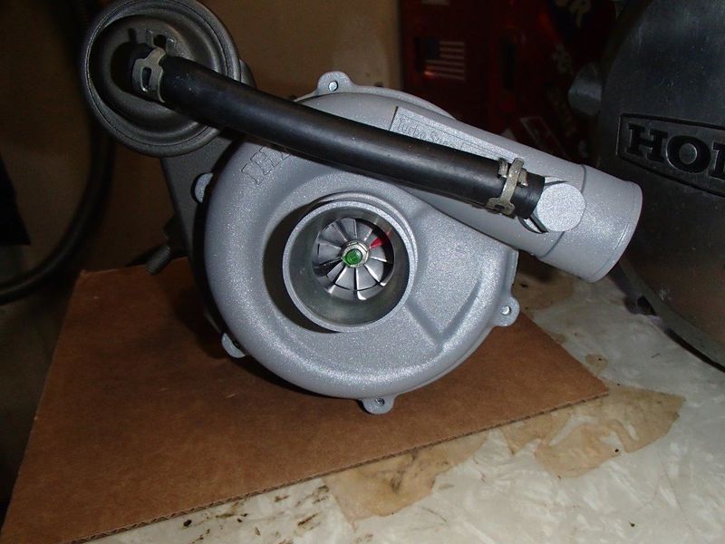
Once you have your turbo back, inspect a few things before installing. Make sure the turbine spins freely. You don't want a loose packing peanut ruining the job. Inspect the hose to the wastegate. These become hard and brittle with age. All hoses and clamps should be replaced anytime the unit is out for service.
Note the paint marks on the compressor wheel. These are used in the balancing.
Parts List
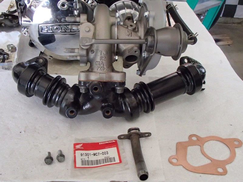
Use a new O ring for the turbo oil return pipe. Part Number: 91301-MC7-003 15.8 x 25.
You also will need The oil feed fitting O rings X2 Part Number: 91304-MC7-003 6.8 x 2.5
Don't skimp on these. An oil leak here is a major fix later. Use the proper parts and you will have a perfect job from the start.
The following can be found on Ebay or contacting mailto:[email protected] or Copper Gaskets Unlimited
Copper exhaust manifold to head gaskets x2
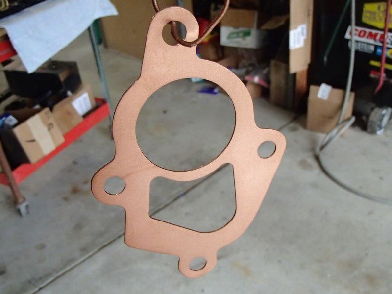
Copper turbo to manifold gasket
Copper turbo to down pipe gasket
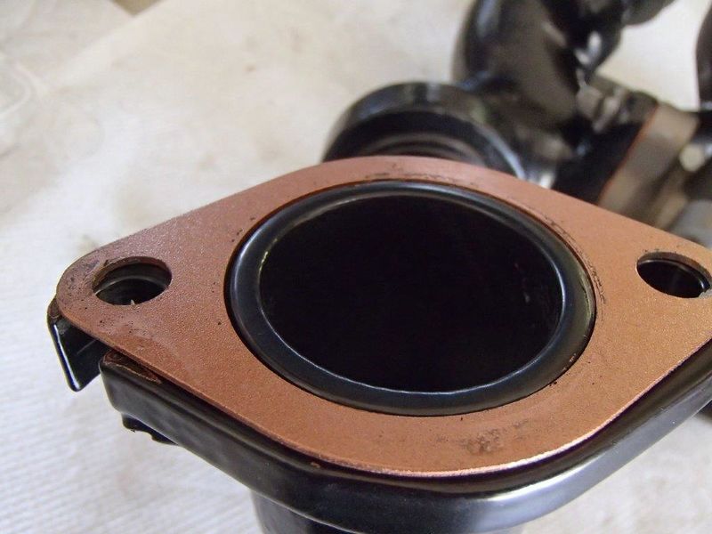
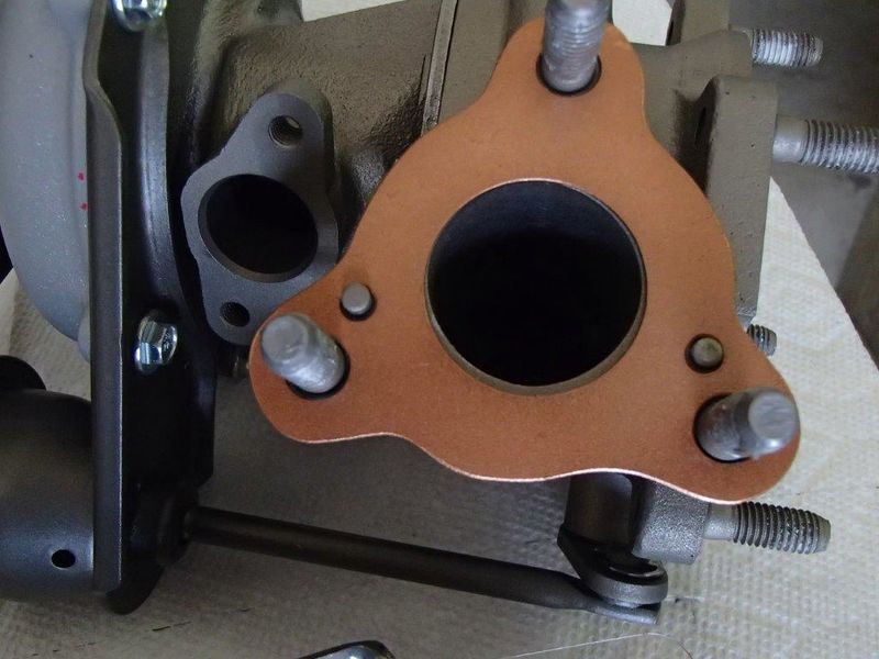
Spray all the copper gaskets with the copper sealing spray. Assemble the turbo to the manifold. Make sure the gasket is placed correctly in the two locating hole pins.
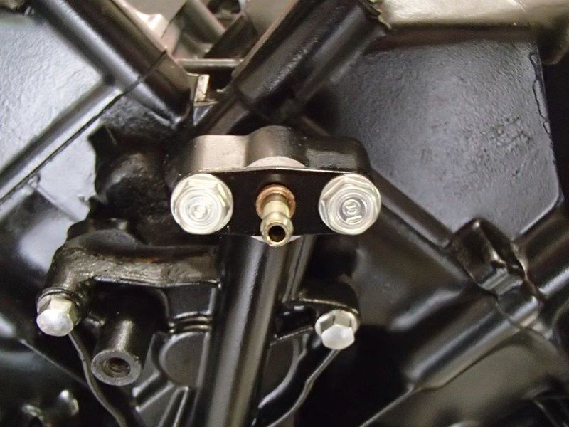
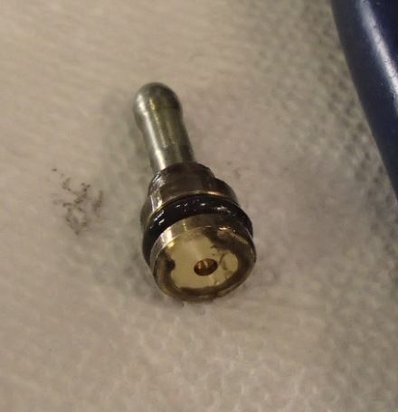
Now is the time to remove the 2 bolts for the oil feed orifice and replace the O ring. Clean the orifice at the same time. This intentionally restricts oil flow to the turbo. Without it, full engine oil pressure will flood the turbo bearings and push past the seal creating smoke in the exhaust and oil consumption.
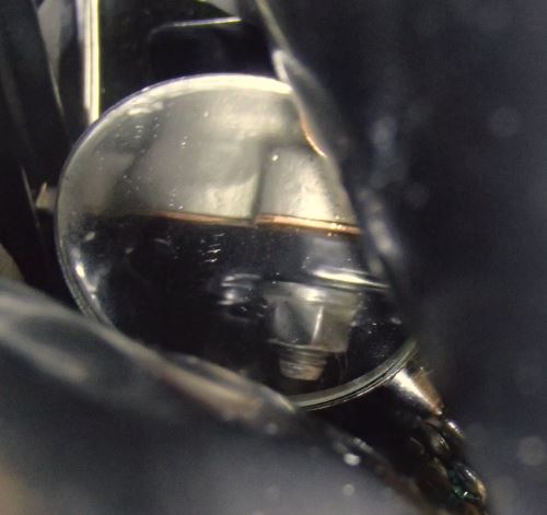
Secure the manifold and turbo assembly to the engine. Pay special attention to the gaps at the copper gasket to head areas. The manifold is difficult to maneuver and you must ensure all gaps are closed when torqued properly. Use finesse here to avoid damaged parts. Here are pictures of a proper joint using a mirror to see the surface flanges.
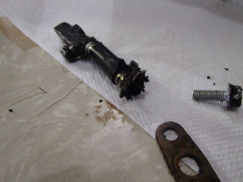
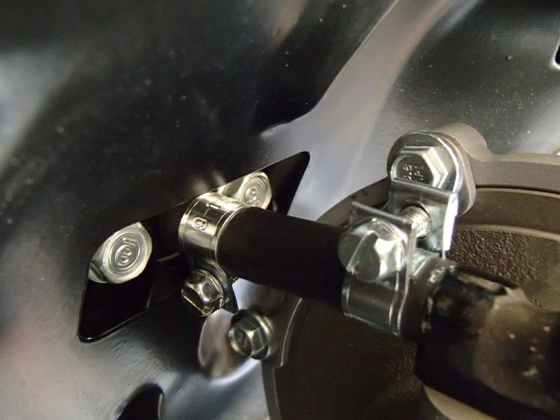
The turbocharger oil inlet hose is one of the Achilles heel of the CX500T. It is buried deep in the engine. It is subject to massive radiant heat. It is only 2 inches long and is sandwiched between the outlet nipple and the turbo inlet fitting. It only has small spring clamps to seal it. The original hose fails quickly. A slow leak at first, just enough for the operator to smell oil, but not see it. Eventually it covers everything as seen in the shield picture above. I searched extensively for the best hose for this application and here is what I found.
Here are the actual SAE requirements for hose manufacturing.
SAE 30R6 hoses are designed for low-pressure applications like carburetors. These can also be used as an emissions hose.
SAE 30R7 hoses are designed for fuel. These can go under the hood and are typically used for low-pressure applications.
SAE 30R9 hoses are designed for high-pressure applications like fuel injection and oil. These are designed to stand up to the environment under the hood.
SAE 30R10 includes hoses that are submerged in fuel. This type of hose is used inside the fuel tank and typically on the fuel pump module. This type of hose uses a special layer on the inside and outside to prevent the core layers from being saturated in fuel. But, don’t use it under the hood. R10 hoses can’t stand the heat.
SAE J30R12 includes low-permeation fuel feed and return hoses.
SAE J30R14T1 is the standard for ultra-low permeation properties. This type of hose is typically approved for use with leaded and unleaded gasoline, diesel, biodiesel, E85, methanol, ethanol and gasohol fuels. These are typically used for low-pressure applications.
"Tube: Black,*High Resistant to fuel & Heat Synthetic NBR Rubber with High Tensile Synthetic Reinforcement Cover: Black, Hypalon, High resitance to weather, heat & fuel, Ozone. Temp Range: -35°C to +125°C Suitable for Unleaded Petrol, Leaded Petrol and Diesel Fuels. Also for Oils"
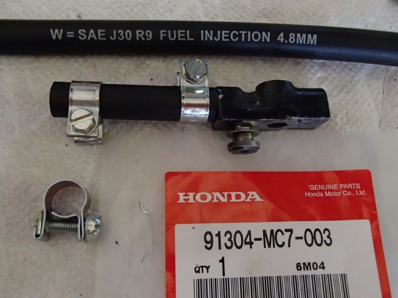
It would be ideal to have a higher working temperature, but in this size, it is not available. I would assume the laws of physics are at work as the diameter decreases. In any event, this should be much superior to the original in all specifications. 35 years brings its benefits. "WP" below stands for "Working Pressure".
A perfect solution. Note full circle clamps
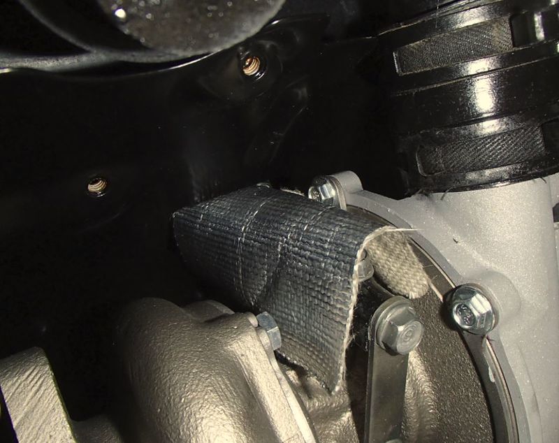
Add your favorite heat reflective material over the hose and its ready for service.
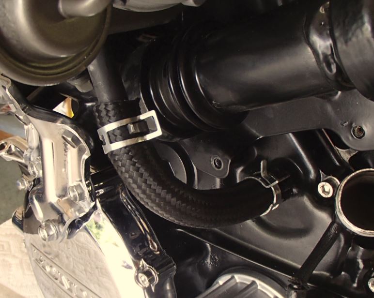
Now you need a new turbo oil return hose. Don't be tempted to use that old ratty 35 year old hose on your nice clean build. Again, found perfect hose after searching the net and ordered Available on Ebay
This was a perfect match for ID This nylon braided hose consists of a synthetic-nitrile inner tube with a partial stainless steel reinforcement inner braid. On top of that, there is a heat resistant nylon sheathing (up to 150 degrees celcius). The Nylon braided hose is significantly lighter and more flexible than the stainless steel braided version. Even better, the hose is designed to handle any fuel (including ethanol and nitromethane), oil, or coolant. Inside Diameter: 9/16" (14.3mm) Outside Diameter: 53/64" (20.8mm) 500 Max PSI
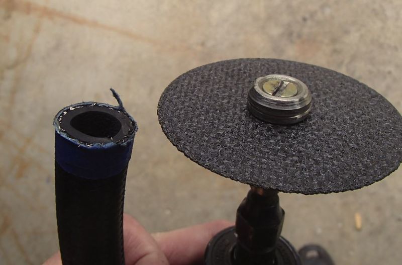
The black braiding matches the original perfectly. Tape the hose and cut the tape in the middle with a thin cut off wheel.
New clamps and you have a perfect replacement that looks original.
Ok, now your assembly should look like this. Its time to make some new shield gaskets. Yours are toast. These gaskets are not critical. Don't be too concerned with the fitment.
Click on the link below and then save to your PC or just print them on standard 8.5 x 11 paper. Cut them out and lay them over you favorite heat resistant gasket paper. This worked well for me. Available on Ebay Mr. Gasket 9615MRG Compressed Gasket Material 1/16x12x18' Sheet
Now, Install your shields and you are ready to go! Ceramic coating is the way to go here on everything except the cast iron manifold. Just spray that with your favorite high temp paint and be done with it. There is no coating that will live on that part. Ask me how I know. I have used powder coating on everything else and it actually survived quite well - including the down pipe and shield! Honda never shipped a turbo that looks as good as this.
Final Note-
Change your oil and filter. Turn your kill switch to prevent engine run. Crank your engine until the oil light goes off during cranking. Let the starter rest 30 seconds. Repeat this 2 more times. This allows oil to enter the turbo, lubricate the bearings, and start filling the circuit while bleeding the air out. Now set your kill switch to Run and hit the starter button. Let the bike warm up and idle until the thermostat opens. This is confirmed when the chrome pipe on the left side of the engine gets hot. Take it out and do some mild accelerations, increasing boost every time. For your first run, hit max boost 2 or 3 times and then take the long way home keeping out of boost mode. This will let the coatings burn off slowly. Never shut your turbo down just after coming off boost. This results in oil "coking" which is a crystallization of liquid into a solid. Next start, the hard fragments hit your bearings and the turbo begins to degrade. Treat your new turbo properly and it will reward you with years of good service.
This site is backed by Number 85, who provide the hosting. If you need a website done, get in touch with them.
