Using a Multimeter
Thanks to Dave F for the following information.
Motorcycle Electrical Troubleshooting
- Revised 7-14-2011
- Introduction
A number of motorcycle electrical problems have been diagnosed on the Honda CX500 and GL500 Forum over the past few years. Many of these problems have been found to be due to the same failure mechanisms. Some of the more common ones are addressed here. This writeup is mostly directed towards the GL500/GL650 bikes because those are the ones I own and am most familiar with. However, much of the material is also applicable to the CX models. Further, the general troubleshooting techniques presented here are applicable to many motorcycles.
- Multimeter Usage
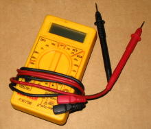
It is very difficult, if not impossible, to troubleshoot electrical problems without proper instrumentation. Without it you're essentially blind to what is happening in a circuit. A multimeter is all that is needed for most troubleshooting and cheap one will work fine. One can be obtained for only a few bucks from places like Harbor Freight Tools. If you're at all serious about tracking down an electrical problem there is no excuse not to have a multimeter. Here is one that I use most often.
Even a simple multimeter has a multitude of measurement capabilities and corresponding settings. But the vast majority of all problems can be accurately diagnosed using only three basic measurement types: Resistance, DC Voltage, and AC Voltage. Since multimeter usage is so important, a few minutes spent reviewing basic multimeter usage is time well spent.
- Meter Lead Connections
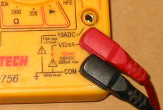
Test leads are provided with the meter. There are often several places they can be plugged into for various measurements but usually there is one configuration that is almost exclusively used in practice. The black (or negative) meter lead should plugged into the jack labeled COM or COMMON or sometimes NEG, depending upon the specific meter. The red (or positive) meter lead should be plugged into the jack labeled V or Ohms or similar.
Often there is a separate connector labelled A or AMPS or similar (10ADC in this example). This is intended for making high current measurements. Current measurements will not be made in this writeup, so don't worry about its usage.
- Resistance Measurements
Resistance measurements are made with the meter function switch set to measure resistance. The measurement unit for electrical resistance is the Ohm, often abbreviated with the Greek letter Omega or  .
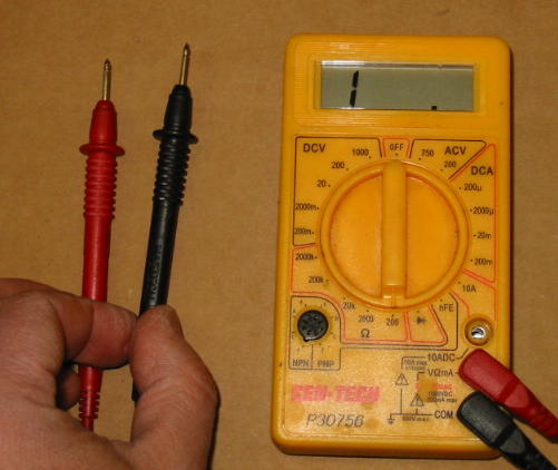
Here the meter is set up to measure resistance. Note the function switch is pointing to 200 in the Ohms section. The Ohm function section indicates resistance measurement, and the 200 indicates the meter will measure resistance values ranging between zero Ohms up to a maximum of 200 Ohms. In this example, the display shows a 1 followed by a blank display. This means the measured resistance is in excess of 200 Ohms. With no connection between the meter leads, an open circuit (or infinity Ohms) exists. Since infinity is greater than 200, this reading makes sense.
.
Here the meter is set up to measure resistance. Note the function switch is pointing to 200 in the Ohms section. The Ohm function section indicates resistance measurement, and the 200 indicates the meter will measure resistance values ranging between zero Ohms up to a maximum of 200 Ohms. In this example, the display shows a 1 followed by a blank display. This means the measured resistance is in excess of 200 Ohms. With no connection between the meter leads, an open circuit (or infinity Ohms) exists. Since infinity is greater than 200, this reading makes sense.
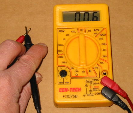
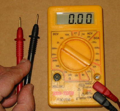
To measure resistances greater than 200 Ohms, the meter function switch needs to be changed. A setting of 2000 will allow the meter to measure resistance values ranging between zero up to a maximum of 2000 Ohms. Note the letter K in the other resistance ranges. K is an abbreviation for "kilo" in the metric system and means 1,000. So if the meter switch is set to the 200K position, it can measure resistances ranging between zero up to a maximum of 200,000 Ohms. Here the meter is set to measure resistance in the range of zero to 200 Ohms. With the meter leads touched together, a short circuit (or zero Ohms) exists between the meter leads. The meter reading indicates 0.6 Ohms. Although this is a very small value it is certainly not zero. In practice, the meter leads themselves have some finite resistance and this probably accounts for most of the non-zero meter reading.
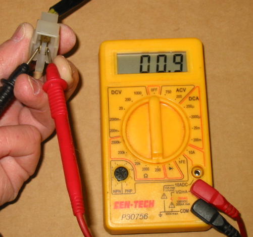
Here the resistance between two stator connector pins is being measured. The meter reading indicates 0.9 Ohms. In reality, the true resistance is probably closer to 0.3 Ohms because the meter leads are contributing around 0.6 Ohms to the measurement as we just determined above.
Resistance measurements are NEVER made on a powered or live circuit. In addition to inaccurate readings, damage to the meter or the circuit itself could occur. When making resistance measurements, be careful not to touch the meter leads. The human body is not a perfect insulator and the reading obtained could simply be your electrical resistance. Lie detector manufacturers rely on this bit of trivia.
- DC Voltage Measurements
Here the meter is set to measure DC Voltage. The function switch is set to the DCV section to measure DC Voltage, and the range position selected is 20. In this case, the meter will measure DC Voltage in the range between zero and 20 Volts. The meter leads are not connected to a DC voltage source, so the meter reads zero Volts as expected.
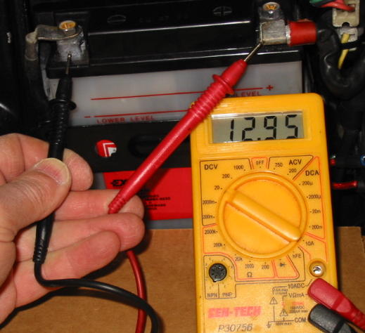
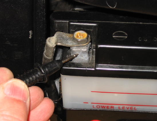
Here the meter is being used to measure battery voltage. The function switch is set as above, the negative meter lead is touching the negative battery post, and the positive meter lead is touching the positive battery cable terminal. The reading is 12.95 Volts.
- AC Voltage Measurements
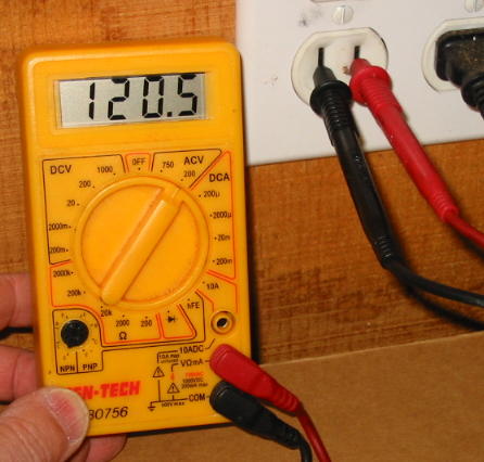
AC Voltage measurements are made in much the same manner as DC Voltage measurements. In this example, the meter function switch is set to ACV and the range selection is 200. Accordingly, the meter is set to make AC Voltage measurements in the range from zero to 200 Volts. The meter indicates that the garage AC mains voltage is 120.5 Volts.
There is no real need to be concerned with the other multimeter measurement capabilities for most general motorcycle electrical troubleshooting.
- Meter Negative Lead Connection
When making most motorcycle DC Voltage measurements (and many Resistance measurements), it is common for the measurement to be "referenced to ground." Quite simply, this just means the negative lead of the meter is connected to a known good ground reference point when making the measurement. In this writeup, whenever a DC Voltage measurement is called for it should be assumed the negative meter lead is connected to ground unless specifically stated otherwise. So what is a known good ground reference point? For a multitude of reasons, my strong preference is the negative battery terminal.
By selecting this point, the negative meter lead is guaranteed to be connected to the most negative power source point, regardless of the condition of other ground connections on the bike. This can greatly simplify troubleshooting in the event that a faulty ground connection exists someplace. As an aside, the valve covers should never be used as a ground connection because they are frequently insulated from the engine block. Now that we are all experts in making the three types of commonly needed electrical measurements, we can move on to using this knowledge to diagnose faults. You can select a desired topic from the list below or go through all of them in sequence. Regardless, I strongly recommend first viewing the Main Fuse and Grounding section as failures here have a very high rate of occurrence.
Here is a situation where the multimeter would be used, again compliments of Dave F.
DC Voltage Testing
In this section, a general approach to DC Voltage testing will be described. Many variations are possible, and there is no single "correct" method. The electrical engineers reading along will probably recognize concepts from the formal circuit nodal analysis method. The approach is probably best explained using an example. A somewhat simplified GL500 horn circuit was selected for this purpose:
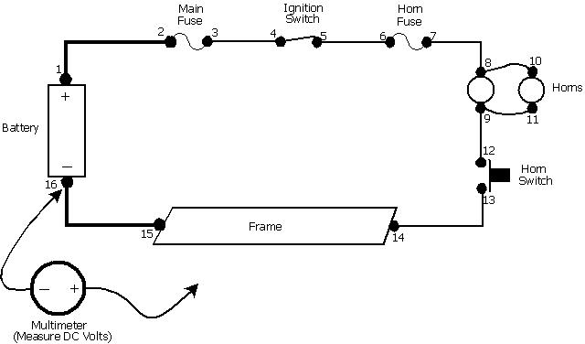
In this simple series circuit, current will flow through the horns when the ignition switch is on and the horn switch is depressed. The multimeter is set to measure DC Volts and the negative meter lead is connect to the negative battery terminal. Voltage measurement points, or nodes, have been assigned and arbitrarily numbered for discussion purposes. With the negative meter lead always attached to the negative battery terminal, and both switches closed, the positive meter lead is used to measure the DC voltage at each of the various nodes. Assuming the circuit is functioning properly, typical representative voltages measured at each point are shown in the diagram below.
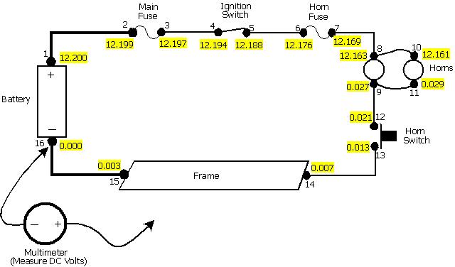
There are some minor voltage drops across the various items comprising the circuit, but the bulk of the voltage is dropped across the two horns. One horn has 12.163 - 0.027 = 12.136 Volts applied, and the other horn has 12.132 Volts applied. Assuming the horns themselves are not faulty, they should both be blaring! Now, suppose there was a malfunction someplace and the horns no longer worked. This time, the measurements taken might look like this:

As before, there are some minor voltage drops across some of the various items, but the vast majority of the voltage drop is across the wiring between points 7 and 8. And the horns have zero Volts across them so they are silent. Wires are not supposed to have any significant voltage drop across them, so the wiring from points 7 to 8 probably has a fault. In fact, this is a real-life example of a failure that had occurred with the horn wiring on a GL500.
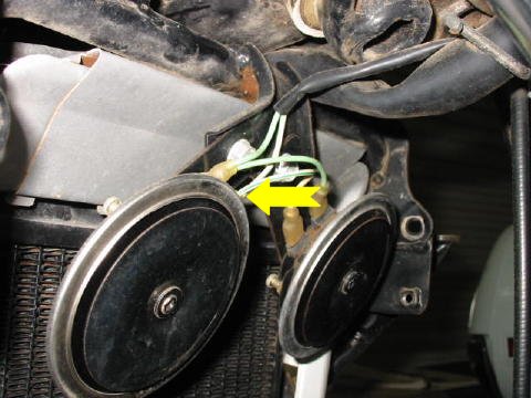
The wire feeding power to the horns had an internal break where shown. The fault location corresponds to point 8 on the simplified wiring diagram. This specific problem is actually fairly common with GL's. The horn wire harness flexes in the wind, and the point of highest mechanical stress is where it attaches to the horn. The failure could have been prevented if a wire tie had been used to secure the cable harness so it would not flex. Let's return to the simplified wiring diagram.
You may be wondering why some items have a voltage drop across them and others don't. Basically, if there is no current flowing through an item with finite resisitance then there will be no voltage drop across it (Ohm's law.) Recall that this is a simplified wiring diagram and circuits unrelated to the horn are not shown. The nonzero voltage drops are due to currents associated with the other circuits (not shown) that just happen to be flowing through shared components (main fuse, ignition switch, etc.) Measuring the voltage at every point in a circuit and then sitting down to analyze the situation is both inefficient and not necessary. A "divide and conquer" approach could lead to a diagnosis much faster. An initial measurement could be taken at some place near the middle, say point 5. The results would be the basis for where to take the next measurement. In this example, point 5 has 12.190 Volts so it would not make sense to measure point 3 next. On the other hand, point 9 would be a good candidate. This simplified circuit is for the GL500 headlight wiring. Only the low beam wiring is shown, and only a few voltage measurements are provided.

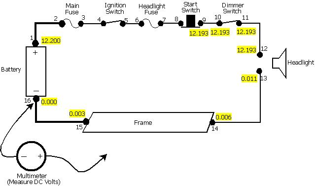
The voltage across the headlight is 12.088- 0.121 = 11.967 Volts. Unless the bulb is burned out, it should be glowing brightly. Now consider the case where the headlight is not working and the following measurements are obtained:

In this case, the majority of the voltage is being dropped across the dimmer switch and the logical and correct conclusion would be that it is defective. But note that the voltage drop across the headlight is not zero, so some small current must be flowing through it unless it is completely burned out (open). It follows that the dimmer switch has not failed in a completely open state, but in a high resistance state. Anyone who has probed a headlight connector with a multimeter knows it can be difficult to access. So why not simply unplug the connector and measure the voltage on the connector to see if there is any power getting to the headlight? With the fault condition unchanged, the result would probably resemble this:
With the headlight disconnected, there will be no current flowing through the dimmer switch. And since it has a finite resistance (even if very high), the voltage drop across it is essentially zero. The incorrect conclusion from this would be that the headlight must be bad - after all, it is getting voltage to it! The major point is, measurements can be expected to change if the circuit changes. Care should be taken not to disturb or modify a circuit while trying to troubleshoot it or erroneous conclusions are likely. Point 14 on the diagram represents where the main wiring harness is grounded to the frame. It should now be obvious why it is so important to have a good solid connection at this location. The wiring diagrams in the factory service manuals are significantly more complicated than the simplified ones shown in these examples. Complicated diagrams can be very intimidating. I often find it helpful to sketch out a simplified diagram before jumping deep into a circuit - remember how the saying goes about not being able to see the forest for all the trees. However, the voltage node troubleshooting concept introduced here can be applied to even the most complex circuits.
This site is backed by Number 85, who provide the hosting. If you need a website done, get in touch with them.
