Turbo Fuel System
The CX500 Turbo fuel system is unique to the CX family. These systems are prone to fuel contamination from improper storage and merit meticulous cleaning and renovation once corrosion has set in. The information in this section is to supplement the Factory Shop Manual - not replace it. In all cases, read through the FSM and become familiar with the procedures and then follow up with this information. Use the FSM torque specs in all cases unless otherwise noted. Let's begin with the tank itself.
Contents
Fuel Tank
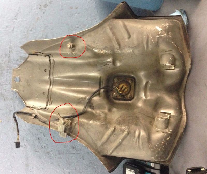
The tank has two petcock fittings from the factory located on each side of the rear of the tank saddles. The right side will have a block off plug and was never used by Honda. These have been used by clever technicians to repair the no longer available petcocks which at times cannot be sourced. By placing a standard petcock available for any Honda with the same thread, the new RH side petcock can be used as a return for the fuel pump! The left hand side will just supply the filter now. This is one option when the original petcock is no longer available.
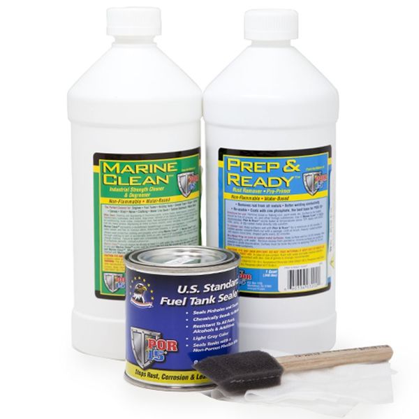
The tank should be sealed using any of the modern multi step epoxy systems which work perfectly when followed per the directions. This will create a "tank within the tank" so to speak. Follow the instructions EXACTLY. No shortcuts, or you will render the tank a filled pile of semi jelled substance. A proper job will yield a lifetime of service. It is not difficult at all. Search for "POR Cycle Tank Repair Kit"
Be VERY careful when sealing the openings. Use multiple layers of coverings should your primary seal fail. During the very last phase, you will be instructed to add the epoxy, then rotate the sealer in its liquid form for about 30 minutes all the while rotating the tank in multiple positions. Now that the epoxy is setting, they instruct you to drain through the petcock opening. If you choose this method, there will be a very thick build up of epoxy that will cure that MUST be removed with a wire brush on a drill in order to reinstall the petcock and filter sock. Instead, flip the tank and drain through the fuel cap opening. Allow to dry thoroughly before moving.
Fuel Sender Operation and Cleaning
The tank sending unit for the fuel gauge is held in place with 4 nuts that secure to welded studs. The O ring for this unit is still available from Honda under part Part Number: 91305-MC7-000 which measures 35.5 x 5
The sender is a simple unit with 3 wires. It contains a pellet that supplies a ground for the "Low Fuel" lamp when the fuel level drops low enough to expose the pellet. Because the pellet is no longer cooled by surrounding fuel, it warms and then grounds the wire to complete the lamp circuit. This process takes 30 seconds to complete once the ignition is cycled on assuming the fuel level is below the pellet.
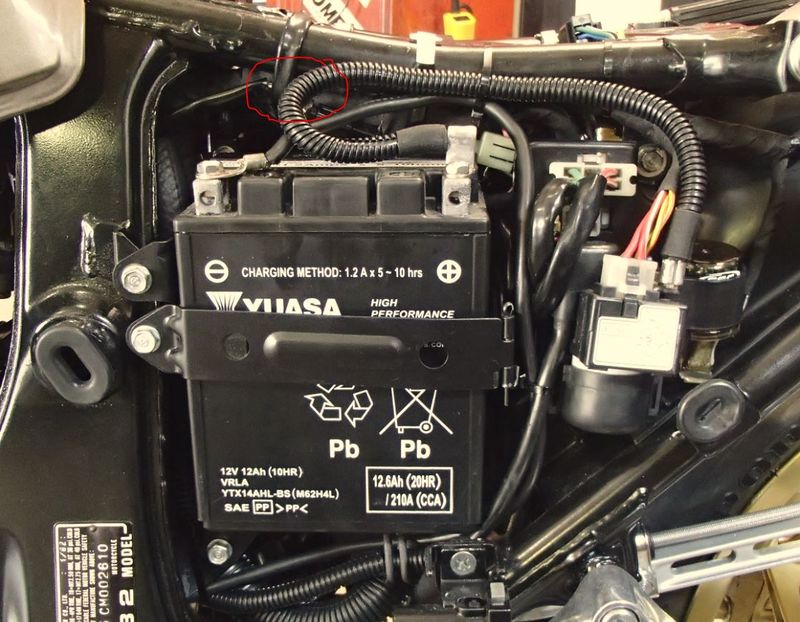
The fuel sender connector is a 3 way connector located directly above the battery under a frame wire retainer wrap. Picture below.
Wiring colors are as follows-
Green = Ground
Yellow = Fuel gauge input
White = Low fuel lamp
The lower the resistance, the more the needle will move toward "FULL". Conversely, the higher the resistance, the more the needle will move towards "Empty" Factory specification values are as follows -
Empty - 71 to 75 Ohms
Half tank - 34 to 39 Ohms
Full - 10 to 15 Ohms
The sender may be cleaned and made functional again if it sat in a contaminated tank with degraded fuel. Remove the sensor from the tank. Carefully remove the resistor cover. You will see a moveable arm that travels across a bridge. This is how the meter can increase and decrease the resistance value sent on the yellow wire to the gauge. You will also see a small stop on each end. These stops are factory adjustable tabs for min/max resistance values.
Using a can of electrical contact cleaner or preferably a can of DeOxit D5 (Available on eBay), spray the finger and wiring thoroughly while moving the float arm. Using an Ohm meter set to the correct range, you can measure the output and compare to the values above. Close is good enough. You will be using the green and yellow wires. Do not probe the female terminals - you will spread them and have connection issues afterward if you do. Instead, either back probe them with your meter ends, or use a terminal of the correct size to enter the female side. This requires experience and spares, so do not attempt unless you are skilled at this procedure.
When back probing, you will have to hold the leads in contact while you check your values. At no time should the reading go "open" while slowly moving the float. If it does, Continue to clean and blow air across the wiring until you get consistent readings. If this still fails, then you will have increase tension on the finger which is a very delicate operation. Some just tweak the arm with a slight bend. Or you can note there is a spring under the finger to keep constant tension. Carefully increasing the nut torque to the finger will increase tension. Only a very small amount is needed. Once you have a consistent reading in the proper min/max range, the meter will work.
Fuel Sender Rebuilding Tips
If your wiring inside the sender that the finger runs across is damaged/broken, here is a solution from the Australian CX500 Forum credit to ONETRACK-
"The Turbo tank that was recently given to me was so rusty inside and out that the fuel sender was also corroded. I rewound the nicrome resistor and now the unit works. I calculated after taking a photo of the resistor and enlarging it greatly to determine the number of turns and from the dimensions of the fibre board that the wire length is about 8 feet (2.43m) and then searched EBay for some suitable nicrome resistance wire at about 26 ohms per foot.. Rewound the fibre phenol board as close each turn as possible by hand and soldered one end, the other end does not have an electrical connection only mechanical.
That leaves us with the low fuel warning lamp pellet. Credit to George in Indiana on the US CX500 Forum for this one.
"I replaced my thermistor with a 20F735. It's dirt cheap from many electronic supply stores. You have to carefully split apart the metal capsule enough to remove it and then install the new one inside. The capsule has holes and acts like a baffle for splashing gas."
Last but not least, if everything checks out, but your gauge keeps reading Empty, it could be a very rare case of a sunk float. The arm may work correctly, and the resistance values my be correct as well as a good working gauge, but if the float doesn't "float", then you still won't have a working gauge. Place the float in a small container of fuel. Note this is hazardous and precautions need to be taken. If the float sinks - you have found your problem. If you use water, it has been known to give false data as the density of the two liquids is not the same. Most will use an automotive sender float at this point and graft it on the old arm. Its not rocket science. You should by now have a working fuel meter and low fuel warning light.
Petcock Rebuilding
So, if you own one of these fine machines, you will fall into one of two groups. Those that have repaired a leaking petcock, (or fuel tap if you are from Europe) or those that will soon be repairing one. These are notorious for leaking. Do not fear however, as parts are available and we have a full "How to" thread right here to get you fixed up.
[1] <---- Click Link to see the CX500 US Forum article with full pictures!
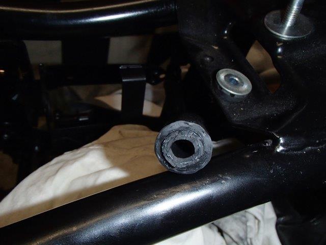
Now after you have the petcock rebuilt, you may need a new "sock" or in tank screen. These were turbo only parts unfortunately and no longer available. One of the CX500 members PIM205GTI has found that a CBX sock will fit after you drill a hole for the return. These can typically be found on eBay: eBay US, eBay AU. Buy the CBX petcock and remove the sock. Picture below.
Fuel Flow Overview
The flow of fuel through the petcock is out through the gray tube to the fuel filter inlet. There is a vacuum in this hose. It passes into and then out of the filter, then to the suction side of the pump then pressurizes the fuel to 36 to 40 psi. Fuel pressure enters the rail where both injectors await a trigger from the ECU. Pressure in the rail is controlled by the pressure regulator that bypasses fuel back to the tank via a hose that connects to the brass colored nipple of the petcock. Here it passes into the long tube and vertically re-enters the tank and exits the top of the sock. The vacuum hose connected to the regulator boosts rail pressure as engine load increases based on boost over spring pressure. The boost acts like a stronger spring. The spring pushes against fuel pressure through the diagram. The extra force of the boost raises fuel pressure during that engine event.
Fuel filter
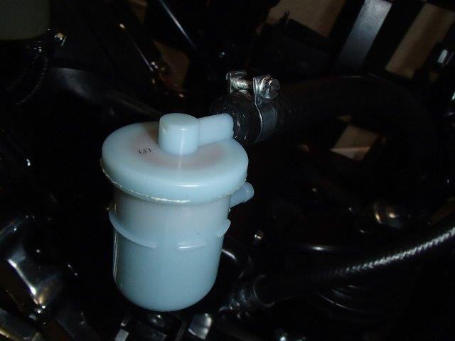
The stock fuel filter is unique to the turbo family. It is no longer available. NOS parts have been known to go for large sums of money when listed. Other than its unique dual side facing ports however, there is nothing special about it. It has a spring loaded bypass like most filters. These plug early and often on these old machines and need an alternative. Here is one that packages in the original space and has the same port design. Keep in mind that any replacement is for low pressure system only. The filter is located on the suction side of the fuel pump, so many modern high pressure filters will be too restrictive in this application. This is also known as Part OMC 5032323, SUZUKI 15410-87J10 is a Suzuki/Evinrude filter for marine applications. . Available on Ebay
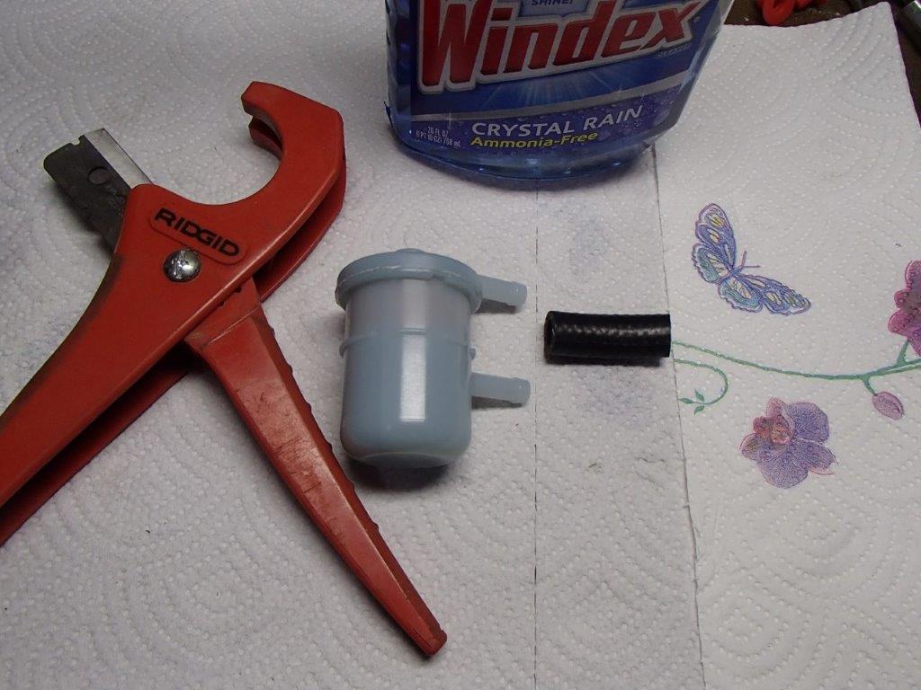
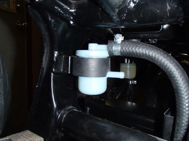
Now that you have your shiny new filter, you will need a secret on how to adapt the fitting size to your turbo effectively and efficiently. Here is my adapter solution to go from 1/2 ID to 3/8 OD. I really dislike adapters and multiple clamps. Takes up space and has a higher leak risk. Cut off a small portion of a new 3/8 ID hose. Apply your favorite glass cleaner solution. This is to allow a lubricant that will evaporate when complete and not leave a residue/slippery condition behind. Now, grab your 1/2 ID fuel hose (I used new) and in one quick motion against a solid object, push the large hose over the small. Trim off any extra that didn't make it flush. Now slip it over your new boat motor filter and clamp. Nice clean look - it will never leak.
Here we have the hose within the hose, ready for install.
Now, make a small notch in the mounting rubber for the lower outlet and mount your new filter in the stock location. Note the large hose goes to the fuel pump.
Fuel Pump
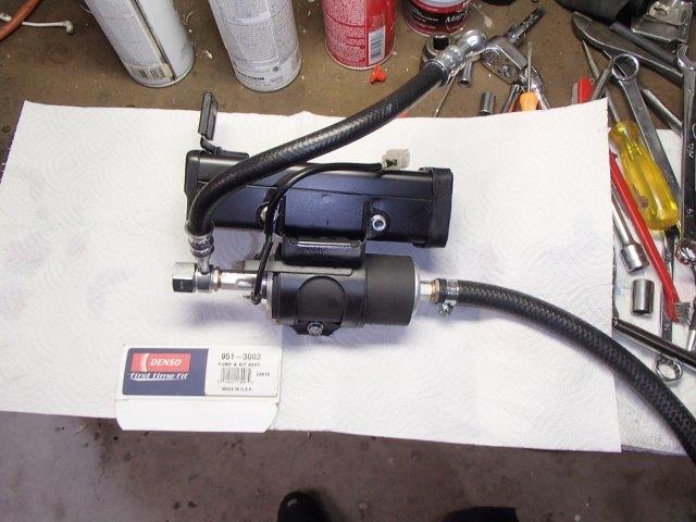
Fuel pump is located under the tool kit mounting box. This is a standard low pressure pump common to early low pressure fuel systems. Nothing special about it. It was originally manufactured by Nippendenso which later spun off to become Denso. An almost direct replacement is available under DENSO 951-3003 Electric Fuel Pump. This comes with all the fittings you need and is a near direct bolt in replacement. You will have to reuse the original jumper harness. Use the new terminals in the kit and crimp them on the old wire. Solder when done to ensure a solid connection. Add shrink tube to reduce corrosion.
Here is the pump mounted to the tool box ready for install.
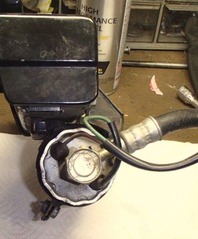
Be sure to connect the wires matching polarity. Green is ground/Negative.
Finished product
One last note on fuel pumps relating to the turbo. They are powered by a relay located under the main sensor farm. It is wrapped inside a rubber sock and impossible to see. These rarely go bad, but high mileage bikes stored in humidity/wet climates have had issues with corrosion. They are interchangeable with the Main relay and located right next to it. This relay is powered from the ECU. The ECU sends out a 5 second prime pulse when key is turned on. This pressurizes the fuel system to prepare for start. Once the engine starts, the ECU receives RPM signals from the 2 NE sensors located behind the water pump. The ECU will again apply power to the fuel pump relay until the key is turned off.
The reason this info is documented is a rare but difficult failure mode that has been documented by the author. These machines are notorious for water pump seal leaks. This is diagnosed by a dribble of coolant running down the LH engine case under the chrome coolant pipe. The coolant comes out a weep hole. When you see coolant - the pump seal has failed. Part of that failure is coolant contaminating the NE sensors which are timed off the camshaft end. When you replace the sensors, polarity matters. Unfortunately, various suppliers wind these coils opposite without regard to color. When you start the bike after this repair, the ECU will run with the polarity incorrect. However, the analog portion of the fuel pump output drive will not work with polarity reversed. The result is a bike that starts, but then runs out of fuel after 8 seconds. The ECU does not recognize the new signal and never reapplies power to the fuel pump relay. The solution is simple. Repin the four way connector for the NE sensors located in the RH sensor farm as shown. Basically, you are reversing the sensor connections and flipping polarity. The bike will now start and run without issue.
Here is the wiring for this discussion. The NL and NR sensors are the timing sensors discussed above.
Here is the connector and solution. Speed sensor solution before shot. Swapped the two yellows and then the blues side to side. Who would guess that prevents your fuel pump from working...
Fuel Injectors
The Turbos use a pair of Denso EV1 injectors. These were developed in the late 70s along with Bosch who collaborated with Nippendenso- later known as Denso. They shared many component designs in the fuel injection development which was rapidly expanding. The injectors are fired sequentially based off the 2 NE sensors on the rear of the camshaft.
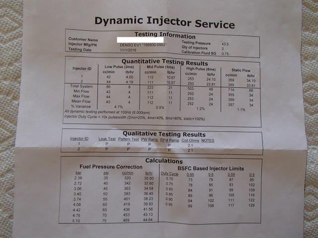
Failure of these injectors is extremely rare. If the bike has been sitting for many years, I can guarantee the injectors will be clogged sufficiently to reduce power significantly. In almost all cases, they just need a professional cleaning and testing. Generally, this can be done for less than $90.00 USD. Any professional injector company can perform this and return them in new condition with a complete print out. Attempts to repair these at home using self made tools rarely delivers long term acceptable results. Do it right. Here is one company that has proven very reliable with quick service and good value -
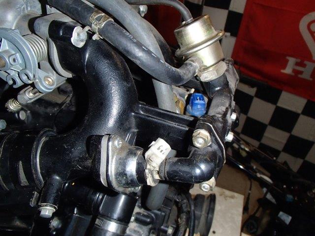
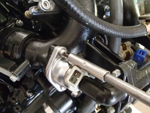
Injector before removal
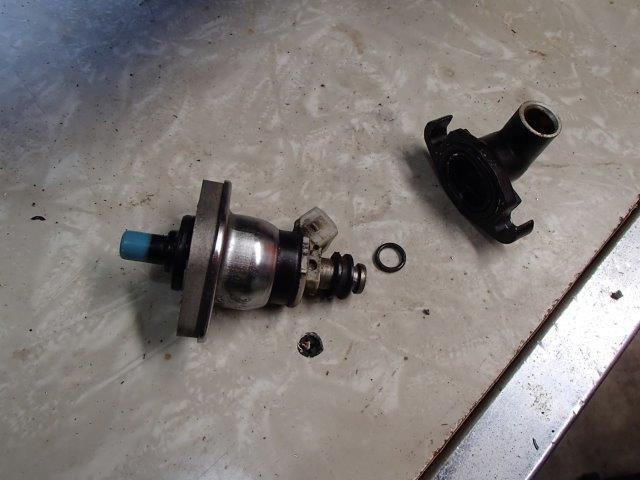
Injector after removal/ with insulator collar in place. Work these off carefully with turning force. Its just a rubber interference fit.
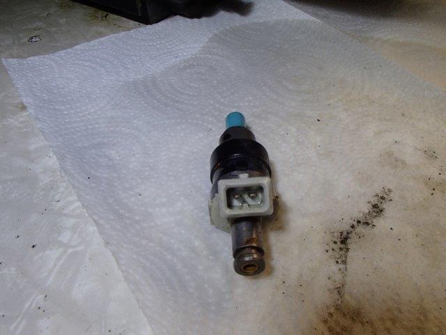
Injector ready for service
Injector Service Sheet sample. Note how close they correlate to each other.
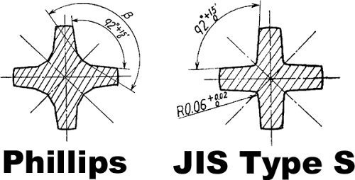
Now, getting the injectors out requires a little knowledge. The screws are not a standard Philips. They are called JIS- short for Japanese Industrial Standard. Most Japanese motorcycle use them. They can be identified by a small dot located between the "X" pattern on the head of the screw. Philips were designed to "clutch out" during max torque for assembly. JIS does not and have a deeper drive cut for better grip.
For more info on JIS see this link (MotoFaction).
Note the dot on the head.
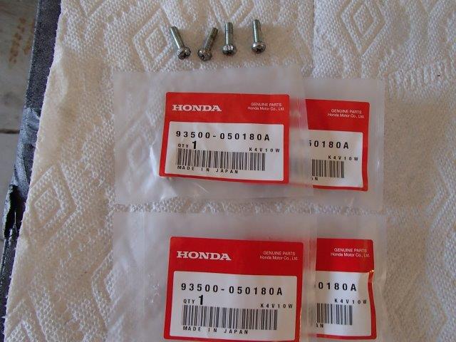
Now, even when you have the correct screwdriver, these are difficult to get out. The injector connector boss blocks you from a straight approach. Some have used vice grips. I use a blunt chisel and hammer to break them loose. Start on an angle and drive counter clockwise just like you would when using a socket. 2 or 3 sharp blows works. Now use the screw driver to walk it out. Discard the screw. New are still available from Honda or you can replace them with hex head screws. These are 5x18 Metric.
Final Assembly notes -
Honda Factory Shop Manual calls for a coating of Anaerobic (seals in the absence of air) Sealer between the insulator and the intake manifold. Any brand will work, no reason to run to the Honda dealer for this. Loctite 515 has been used with good results.
After coating the injector and rubber insulator with a silicone grease, you may twist the insulator and chrome cover onto the injector. Use of a new injector seal to manifold O ring is recommended. Ask your injector repair center for new ones when sending in your injectors. Now you can install your new JIS screws. It is possible to rotate the injector so you have a straight shot at the screws, tighten the screws, then rotate the injector to vertical position which is stock. This is now possible because you have that nice silicone lube between the insulator and injector. Makes life a little easier.
Sealing Washers
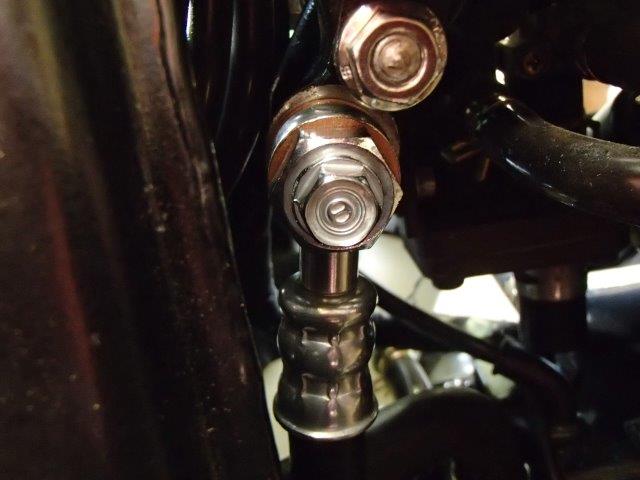
I spent some time running down new fuel banjo bolt aluminum washers for the inlet fitting. There are a few that came close - but none exact as the original size. Here is what I used.
Available on Ebay (Qty 5) 12mm x 20mm Aluminum Crush Washer for your Oil Drain Plug Honda Yamaha
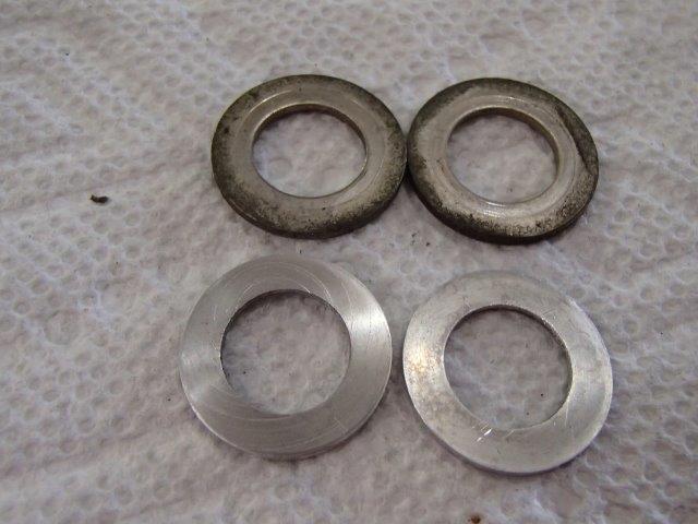
The original size is 1.5 mm thick / with OD of 21mm / ID of 12.25mm
The ebay size is 1.4mm thick / with OD of 19.9mm/ ID of 11.87mm
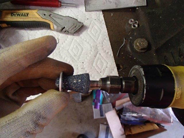
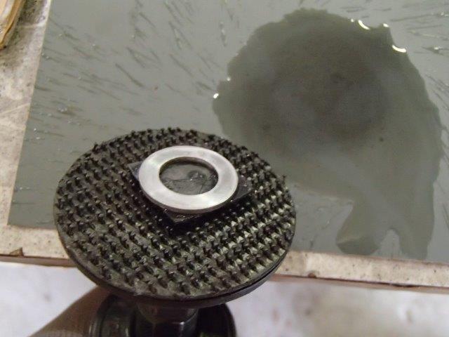
So.. the new washer is tight fit to the bolt. I used a rotary taper stone to open it up. That means I also had to refinish it to remove the burr edge. After messing around a bit, I came up with an idea. I chucked my 3M sanding pad which has Velcro as a base in a die grinder, then stuck a small piece of cloth Velcro with adhesive to it. I stuck the washer on the adhesive, then took it to 1000/ 1500 / finally 2500 grit wet sand paper! Use low RPM and water. It keeps the adhesive cool so the washer doesn't fling off. Gave me glass finish in seconds. Do not press down- let the spinning do the work. I then hit the washers with copper head gasket spray Available on Ebay and let that set up. Installed and ready to go.
Enlarging hole slightly
Adhesive Velcro stuck to 3M disk
New washers ready for install. Note witness marks in old washers. These WILL leak.
Installed and leak free
Final Note
Now repeat after me - "I will never leave fuel in my bike without replacing it longer than 4 months - scouts honor" During winter months, I go out and cycle my key several times just move fuel through the tank/filter/ pump. It takes just a minute, and helps keep build up from starting. If you use a stabilizer, make sure to drain the fuel when you bring the bike back into service. Never run a turbo on stabilized fuel under boost. It does impact performance. Dump it and replace with fresh fuel.
Advanced Discussion Details
This excerpt is from the CX500 forums as quoted by PIM205GTI who is without question the most knowledgeable person alive on these systems. Info is for your reference and understanding.
"Honda apparently were so worried about drivability and functionality that they pulled out all stops on the design. Important for any fuel injection system is to measure air flow, well on the CX500 there was simply no room available to place a MAF sensor so they had two options:
Speed Density - injection time mainly based on RPM and Manifold pressure
Alpha-N injection - injection time mainly based on RPM and Throttle opening
So what did they do , they used both !
Speed density for low throttle openings and Alpha-N for high throttle openings.
But even that was not enough, they added a second computer processor to keep eye on the sensors if the outputs of the sensors were not within specification the ECU would go into limp mode so that the engine wouldn't be damaged but still be driven home safely.
Further things to consider : - fuel injection is sequential - ignition is analog and has boost pressure compensation - CX650 has digital ignition - No wasted spark - V-twin is odd firing and odd sequential injection - trigger wheel for ignition has only one tooth - trigger wheel CX650T has 9 tooth but no missing tooth
All of this makes this an odd ball in Fuel Injection control land
I would love the have an eprom emulator running to change real time the parameters. Problem is that the eprom is a 2716 (2K) eprom and is not supported by Moates and probably the software will also not support dual injection modes.
I would like to run something like a Megasquirt. Problem it support for V-twins is not so good. It can run a V-twin but then you lose different options on peak and hold injection driver. It doesn't support a dual mode injection.
I think anybody who wants to change the fuel/injection system does that to get more horsepower out of the engine. Because the OEM system is already so good the replacement should be better.
My requirements for a full racing replacement system would be roughly
- Sequential fuel injection - End of fuel injection pulse control - Dual mode speed density + Alpha-N - Wide band Lambda sensor - Odd firing ignition with dwell time control - Intercooler temperature output/input - Turbo RPM sensor output/input - Electric wastegate - Electric Turbo blow off valve - Fully independent fuel and ignition timing on each cylinder
That being said so far I know roughly how the fuel injection timing is done and which tables in the Eprom have to be changed. A lot of data inside the eprom I am still unsure about such as voltage compensation, atmospheric pressure compensation etc "
This site is backed by Number 85, who provide the hosting. If you need a website done, get in touch with them.
