Testing your stator
Thanks to Dave F's site for the following information
- The Stator Connector
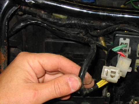
The stator connector is the connector with three yellow wires. This is where the alternator stator (located inside the engine) is connected to the regulator/rectifier module (located under the battery tray on GL bikes).
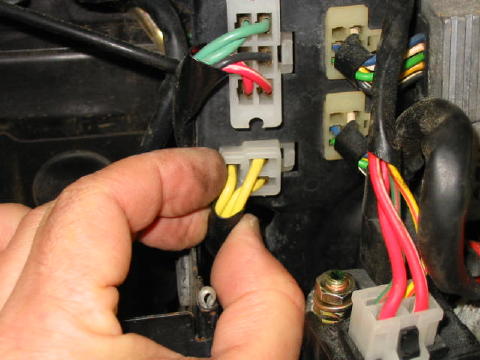
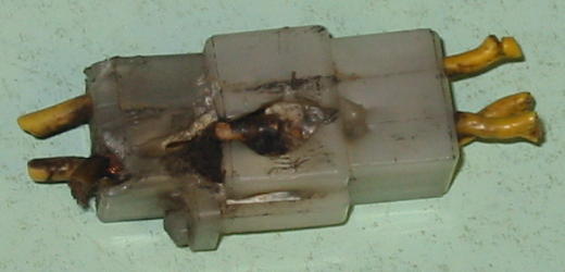
The stator connector has a long history of problems on many Honda bike models. In addition to charging problems, fires have started when this connector has malfunctioned. I'm aware of one CX turbo bike that was completely destroyed by fire when this connector failed. This particular stator connector shows evidence of arcing and severe overheating. Thanks go to Honda CX500 and GL500 Forum member Dave from Slippery Rock for sharing this example.
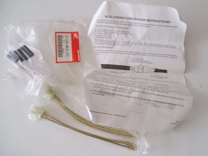
Unplug the connector and closely inspect both halves for evidence of overheating, arcing, corrosion, and broken or frayed wire ends. A good solid electrical connection is absolutely essential here for all three wire junctions. If there are problems, one time-honored and widely accepted repair is to remove the connector entirely, solder the wires together, and cover with heat shrink tubing. Alternately, Honda sells a connector repair kit (part number 31105-ML8-305) containing both connector halves and heat shrink tubing. In either case, soldering is necessary. An excellent tutorial for solder-splicing wires can be found here.
- The Stator
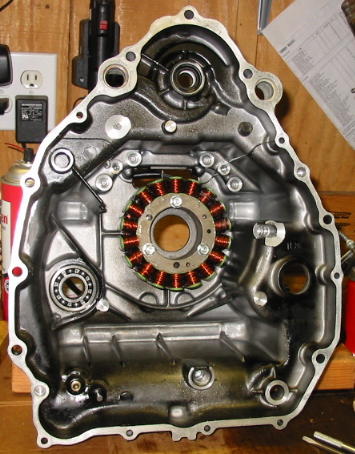
Stator failures are fairly common. Unfortunately, the stator is located inside the rear engine case. If replacement is necessary the engine must be pulled and disassembled to gain access to the stator. Fortunately it is not necessary to go to all this work to simply test the stator.
When testing the stator, multimeter measurements are taken at the stator connector with the connector unplugged. Make sure you are taking measurements on the stator connector half that goes to the engine, not the connector half that goes to the regulator/rectifier. Tug on the wires to trace where they go - do not make a false assumption about which end is which. A simple mistake in selecting the wrong connector half could lead down an erroneous troubleshooting path so it is important to confirm what is being measured.
- Stator Resistance Checks
First, measure the resistance between each of the three stator connector terminal tabs and ground. Set the meter function switch to the highest resistance range possible (2000K in my case). The negative meter lead should be connected to the negative battery terminal. Measure each of the three stator connector terminal tabs in turn using the positive meter lead. A good stator will have infinite resistance to ground (open circuit or no continuity) from any of these terminals. If the meter reads anything else, the stator is defective. Next, measure the resistance between each of the three connector terminal tabs. Set the meter function switch to the lowest resistance range possible (200 in my case). In this case, the negative meter lead is not connected to the negative battery terminal but is used to measure from one stator connector terminal tab to the next with the positive meter lead as shown in this photo. (This is the same photo seen earlier in the multimeter section.)
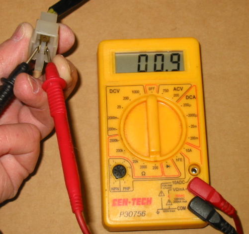
A good stator should measure well under one Ohm for each of the three possible test connections. As described in the multimeter section, be sure to consider the residual meter lead resistance when making this measurement - we are interested in the actual stator wire resistance, not that of the meter leads! If any of the three measurements are above 1.5 Ohms, the stator is defective.
- Stator Voltage Checks
Assuming the stator resistance checks are good, the next thing to check is the stator open circuit voltage. The stator connector is also unplugged for this measurement. Set the meter to measure AC Voltage with a range selection of at least 100 Volts on your meter. Start the bike and adjust the throttle so the engine is running at about 2000 rpm. Measure the AC Voltage between each of the three stator connector terminal tabs, tab-to-tab as in the previous resistance measurement (not tab-to-ground). Write down each of the three measured voltages. The actual voltages measured are not so important, and they will vary with engine rpm over a range from about 40 Volts to 70 Volts. However, it is important that the three measured voltages are approximately the same value. A gross mismatch is a strong indication of a shorted stator winding. A typical set of measurements for a good stator might be 53, 52, and 54 Volts. For a bad stator, this could be 18, 24, and 12 Volts. In the latter case the voltage is both grossly unbalanced and low. A stator can pass the resistance checks but fail the voltage checks. In this case, one or more windings are shorted to themselves. Conversely, a stator can fail the resistance checks and pass the voltage checks. If the stator fails either set of checks it is defective.
- Hot and Cold Stator Checks
The stator resistance and voltage tests should be performed both when the engine is cold and after it has warmed up to normal operating temperature. The stator windings can develop a short or open circuit as a function of temperature when they contract and expand. The tests are not complete until you've performed them under both conditions.
- Stator Replacement
If you've positively determined that your stator is bad, there is a strong chance that nothing else has failed. That is the good news. The bad news is that the engine must be pulled and disassembled to gain access to the stator. Since this is a significant task (although not really difficult), it makes sense to take care of other things within the engine that may also need attention while it is apart. The other big items are the cam chain and water pump mechanical seal, and the three together are often referred to as the "triple bypass operation." In addition, there are several seals and o-rings that should be replaced at the same time. It is beyond the scope of this writeup to address all these items, but they are well documented on the Honda CX500 and GL500 Forum. In particular, check out the Quick Reference thread and the Triple Bypass Parts thread. You will also want to get a copy of the Honda factory service manual for your bike - don't even think of digging into your engine without it. A pdf copy can be downloaded for free from here. Should you have any questions, post a query on the Honda CX500 and GL500 Forum. The forum members will be eager to help. There are several sources for replacement stators. More information can be found here. The replacement stator will be provided with a new connector half, including the shell and terminal tabs. It should be the last thing installed after the engine has been replaced and the stator wires have been routed to the mating stator connector half. I recommend the new terminal tabs be both crimped and soldered. Unless you have the correct crimp tool it will be difficult to get a reliable connection otherwise. The last thing you want is arcing and related evils after the miles have accumulated and the wires work loose under vibration. The original plastic connector shell has a locking tab to keep the connector halves secured together. Often the replacement connector shell is missing the locking tab. If this is the case, you may want to re-use your original connector shell if it is otherwise undamaged. The old terminal tabs can be easily removed by using a jeweler's screwdriver to press on their sides while gently pulling from the rear. Look closely at the new terminal tabs to see how they are secured in the connector shell.
This site is backed by Number 85, who provide the hosting. If you need a website done, get in touch with them.
