Old Triple Bypass Page
Contents
- 1 Triple Bypass - FADM Stern GNSF
- 2 Parts List
- 3 Old Parts List
- 3.1 Here is a post detailing all the parts required for a Triple Bypass. Not all of these are necessary to replace, but all should be examined.
- 3.2 Here is a post from Shep's site on how to do a "engine in bike" mechanical seal replacement. Several hints and tips that are useful.
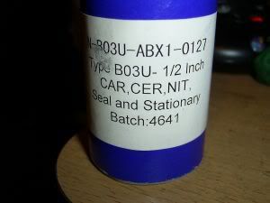
- 3.3 Note: If you use the Yamaha Seal(Part No:11H-12438-10-00) the glue they use is harder, so heat underneath the metal cup until it sizzles and be careful and don't force it.
- 3.4 Important! It MUST be there and also if it is there you do NOT want to place another one on top of it!!!
- 3.5 Update Note 1-20-13: It is now recommended that the copper washer be replaced, rather than annealed. The reason is that altho annealing restores the malleability (softness) of the washer, it does nothing to affect the thickness of the washer. A washer that has been previously installed may not allow the impelled to be firmly pushed onto the splines. A loose impeller will allow the splines to abrade and there may be a noise associated also. So, for the fifty cents, just order a new one!
- 4 WHOA
- 4.1 Before you slide that rear cover back on, do this quick check of the pulsar coils. If they are reversed, the bike won't run, or run very poorly. He is a post from MurryF explaining how to check:
- 4.2 If you have the stator and pickups unbolted from the back cover, it is possible to reverse the way the pickups are bolted into the back cover and it goes like this (LOL) the pickups are marked R & L http://cx500forum.com/forum/attachments/technical-help-forum/8255d1392657238-spark-fuel-still-no-flame-help-me-somebody-l-r.jpg%7Cthumb%7C647x366px%7CName: L&R.jpg BUT THIS IS WHEN FACING THE FRONT OF THE BIKE so in other words when the cover is installed. When you remove the rear cover they look backwards just like the picture, BECAUSE YOUR ARE FACING THE BACK OF THE BIKE I have seen many times when people get their stators back from Gary or when they have had the motor apart, they forget how they came out, so they install the right on the right and the left on the left SO THEY NOW HAVE THEM BACKWARDS.
- 4.3 Now, take the rear case and have ONE MORE LOOK to make sure you are done in the engine and the shifter lever teeth are properly meshed (at bottom of picture above). Now careful slide the rear case on and push and/or lightly tap into place. Once it’s flush and on, check with a flashlight that the gasket stayed in place all around the engine, then tighten the bolts finger tight. Once all the bolts are in and you’re happy the gasket is in place well, get the shifter and shift up and down through the gears again. Better to find a problem now before getting the bike back together. Now, turn the engine through several revolution using the front engine bolt, and make sure there is no binding or rubbing. If it works fine, tighten the rear case bolts and check the gear shifting and engine spin one more time. Make sure the engine turns over like it did when it was stripped, only valve spring tension in spots when turning it. Below you can see the rear case back and a bit of the new stator visible.
Triple Bypass - FADM Stern GNSF
To start the triple bypass, you must first remove the engine from the bike. Removal is listed in the manual and is pretty straight forward. Once you have the engine out, you will need to remove (drain) the coolant and oil, or you will get a nasty surprise when you start. The most important thing to do now is to stay organized. Before starting gather together something you can keep the parts in and separated (I used sandwich zip lock bags), so you know what parts are part of WHAT assembly. Also, a camera is INVALUABLE to doing this work, as you can take pictures after every step to keep a record. This makes it a lot easier when it comes time to put the engine back together.
Parts List
External link:
Organised parts list available here: Click here
Old Parts List
Here is a post detailing all the parts required for a Triple Bypass. Not all of these are necessary to replace, but all should be examined.
I suspect that in most instances, the blue part numbers are not replaced.
CX650 and GL650 parts differ in important ways - see Murray's post here: LINK TO FORUM
|
|
I want to organize a General "triple-bypass" parts list . I've been looking but can't
seem to find an easy to read list with just part numbers. note:There are also "substitute" parts, like making your own gaskets and maybe getting o-rings from a kit but this is not that list. This is a OEM list. From here you can decide what will work best for your bike.) But since I've never done it I am not exactly sure what parts are parts you need and what are parts you might need. Please let me know what should be added or removed from this list. thanks! gee red=parts you probably should replace blue= parts you might need to replace all numbers in blue or red are OEM part numbers In General... Whenever the CX500 engine is removed one will need: a service manual and what I'd like to call the "CX500 Chorus" because like a song it's always going to be back to this point. i. 2 exhaust gaskets between header and manifold 18291-286-306 ii. 2 h-box to muffler gaskets 18392-MG7-750 iii. 2 exhaust to h-box gaskets 18392-MK4-000 In addition, if your going to open the rear case for a particular service you will need. In general: iv. new oil and filter v. new anti-freeze ( coolant) vi. 5 water pipe o-rings (21.9x2.3)mm 91301-MB6-003 ( If you are not removing the thermostat housing and crossover pipes, you will only need one O ring for the transfer tube) vii. 2 water pipe o-rings (23x2.8)mm 94608-50000 viii. 1 rear cover gasket 11394-449-306 ix. 2 rear cover o-rings (23x2.8)mm 94608-50000 x. 2 rear cover dowels (10x16)mm 94301-10160 Stator servicing will require you sing the Chorus plus: xi. 1 rewound stator from a reputable source --------------------------------------------------------------------------------------------------------------------------------- A leaking Shifter Seal will require : xii.1 shifter seal (14x26x6) 91251-ZW5-003 plus all of the above minus the stator. note: this can be also done without removing the rear cover. --------------------------------------------------------------------------------------------------------------------------------- Mechanical seal job will require the "chorus" plus:
Honda part number 19217-611-000 is not suggested by many, because of price, and possibly size; OR the much recommended Yamaha mechanical seal part number 11H-12438-10-00 that cost less. Scroll down to a post by DaveF, he has supplied some excellent must-read links for more info on this subject. #13. 1 oil seal next to mechanical seal (18x28x6) 91202-283-013
#1. 1 water pump cover gasket 11396-415-000 (This is actually a O ring type gasket, and most times can be reused.)
#16. 2 dowel pins at water pump (10x16)mm 94301-10160
#4. if impeller is damaged replace 19215-415-010
#11. 1 washer 6mm 90441-706-000 (I would order a new copper washer rather than anneal the old one, less than a buck)
#12. 1 washer 10mm 90453-415-000
----------------------------------------------------------------------------------------------------------------------------------
#3. 1 cam chain 14401-MA1-013 #4. 1 cam chain tensioner 14500-470-751 #10. 1 cam chain guide set 14600-415-305 (part #12 chain guide is NAL and a used one will have to be found if replacement is required)
#6. 1 tensioner spring 14515-415-000 #1. 1 cam chain sprocket 14321-415-000 |


------------------------------------------------------------------------------------------------------------------------------
Once the engine is out and drained of all fluids, you will need to get the rear case off, but a couple of things need to come off first. First, you need to remove the advance pulsar cover from the rear of the engine. My bike (a 1982 CX500C) has Transistorized Ignition. The pulsar cover is a little different on the CDI engines (more of a flat plate) but they are in the same place. Below is a picture of the advance unit with the cover removed. As you can see by this picture, there is some nasty brown crystallized crud in there. This turned out to be “crystallized coolant/oil” that was created by a leaky mechanical seal and a failed oil seal.

Below you can see this gunk inside of the advance unit cover. Don’t worry if you find a bit of oil inside, as there is an open area into the rear of the engine where oil and vapor splash around. You can see on the picture that the “breather” connection for the TI bikes comes off this case, so I’m not surprised to find a bit of oil in there. You can also see one of my sandwich bags marked for the advance Pulsar parts when they are removed.

Next, you will have to remove the water pump cover, so you will need to first remove the water tube from the housing that feeds the bottom of the radiator. Once that is off you can remove the water pump cover. The cover is held on with a few bolts AND has two locating dowels, so the cover MUST come straight off. Sometimes they are stuck well and won’t budge. I use a large blade knife (like the breakable blade Olfa knives that you can extend the blade way out) and place the edge in where the gasket space is between the two mating surfaces. Carefully tap the blade into the gasket area keeping the blade “Parallel” with the gasket. The edge on the blade is at an angle that will prevent it from contacting the metal faces if it’s tapped in parallel. Tap it in about a ¼ “ as you don’t want to hit the dowels (will wreck the blade). The move the bade over to the next adjacent area and repeat. By the time you have gone a little more than ½ way around you will see the gasket seal let go, and then the cover will come off easy. Remember, the case must come out straight due to the 2 dowel pins. If you must “pry” it forward, try to do it with a plastic tool so as not to mar the gasket mating surfaces. Be gentle and take your time.
As you can see below, it’s pretty clean and gives you a great view of the water pump impeller. Make sure the impeller is intact and undamaged, as even a broken fin can effects its operation.

You will now have to remove the impeller by removing the nut that attaches it. Note the copper washer under the nut, don’t loose it. Once you remove the nut and washer, the impeller will pull off. It sits on a splined shaft so you may need to work it a bit to get it free. Be REALLY careful you do not damage any of the fins on it as it will destroy the impellers ability to function properly.
Below shows the impeller removed along with the nut and washer. Also shown are the splinted shaft and the mechanical seal’s “polo mint” with the mechanical seal behind it (this one is destroyed). If you look carefully at where the polo mint meets the shaft, you can see a “washer” just in front of it. This is a special washer that fits “inside” the polo mint and acts as an adapter to fit the mints larger inside diameter to match the shaft diameter. BE CAREFUL, the washer usually welds itself to the polo mint, and will have you spending hours later looking for it (as it looks like its PART of the polo mint. Just remember, the polo mint has NO metal parts, so if you see something metal you will know what it is. Even though you won’t reuse the mint or old seal, save all the parts for now (and separate and save that washer).

You can see below the mechanical seal guts (as the seal self destructed) in the order they came off the shaft. You can also see clearly where that special washer (which you MUST save and reuse) is stuck to the polo mint. You can also see the remaining parts of the mechanical seal still on the shaft (rubber boot part and cup). Keep all the parts from the water pump in a separate bag marked “water pump”... and don’t forget to take pictures. If you look at left side of the picture you will see where one of the water pump screws has broken off (was broken earlier when tightening it to stop a leak, which was actually from the weep hole). Fortunately I was able to get the piece out easily.

Now, you will have to remove the advance unit, BUT, before you do (TI ignition system only require marking as the CDI systems have a key) MARK its location by scribing a mark on the base plate and the rear case. The advance unit can be turned which effects the advance timing, and if it’s not put back in the right spot the bike won’t run very well, if at all. Once you have the lines scribed (I prefer to scribe as opposed to ink, as a scribe mark WON'T rub off). You can remove the center bolt that holds one the lobe piece onto the crank shaft. The lobe piece sits on the crank with a key, so getting it back in the right spot is easy. Once the lobe piece is off, you can remove the two screws that hold the advance unit in place and remove it. Keep all of the parts in a bag marked “advance unit” ... yep take pictures.

Once you have the advance unit out, you can remove the rear case. Remove all the bolts and check to make sure you got them all (15). The rear case also has 2 locating dowels (one bottom left, one near the top right) AND two large water transfer dowels (top at each side of the water pump housing) as can be seen in the picture below. You will probably need to do the ‘knife blade in the gap” as above to break the seal on the rear gasket, again take your time and keep the blade parallel to the mating surfaces. Once the rear case releases you must keep pushing the gear shift shaft back in toward the front of the engine (see picture below, the shaft is located on the left side just below the crank shaft [hidden by a bracket]). If you don’t keep pushing it in as you work the case off, that shaft will come out and drop the shifter lever out of position. If it does pop out on you, don’t worry they are not hard to put back.

Once the cover is off, you will see the inside of the engine.

OK, so now that the rear case is off, let’s deal with that first as this is where the stator is mounted. As you can see in the picture below, there is a lot of crystallized crud inside the rear case. Fortunately I didn’t migrate around the engine and the rest of the engine was pretty clean. Again, this is what can happen with a bad mechanical seal, which usually kills the oil seal after a long period of leaking. You can also see the stator which looks pretty good. I searched over it for an hour and could not find any visible insulation damage, but the meter told me otherwise. The windings were good, but shorted to the case (ground).

Below is a better picture of the crud formed from the seals going bad. If I had not had to replace the stator, this would have eventually grown, migrated and destroyed the engine. If you need to pull the rear case, ALWAYS replace the mechanical AND oil seal so you don’t have to do this all again.

Now it’s time to remove the stator. It is held on with three bolts which are in pretty tight, but easily removed with a ratchet and socket (use ONLY 6 point sockets, 12 point ones have a habit of destroying heads). Once these three bolts are out (and saved in a bag) the stator will come free and you can then remove it (will have to pull the rubber grommet in the rear case out to free the wires).
Below is a picture of the old stator removed, and you can see the rubber grommet that presses into the rear case (you WILL need this so don’t destroy it). This stator is a G8 type (for charging only), but if you have a CDI engine it will be a G47 (will have two high voltage coils on it)

Before you mount the new stator you will need to do a couple of things. First you will have to cut the wires on the old stator near the grommet so you can salvage the grommet and pull the new wires through it. Once that is done you can feed the new stator wires through the grommet. Now, before you mount the new stator it’s a good idea the grind down the sharp edges on the three mounting posts on the rear case (the ones the three screws go into). I used a dremmil to “round off” the edges so that there is less chance of a future ground being formed between the edge and the stator coils. It isn’t mandatory, but since you’re already in there it’s a good idea. Below is a picture of the new stator mounted in a cleaned up rear case. You can also see the new mechanical seal I have installed, but more about that later.

Now that the stator is in, let’s move over to the engine and get the new chain on. Below is a picture of the crud that also stuck to the cam shaft sprocket (right behind the water pump). If you look to the right of the cam shaft, you will see the cam chain tensioner. If you look carefully at the large shiny bolt (that’s the tension adjusting bolt that pokes through the rear case) you will see a slight slot gap below it and a fraction of one above it. This chain is basically shot (you will see what I mean when the new chain goes on).

To get to the timing chain, we will have to remove the rotor. You will first have to remove the bolt on the front of the rotor, which can be a pain considering the crank shaft will want to move when you try to loosen the bolt. Some people will use a belt wrench on the rotor to hold it still, but I decided to try it without. With the plugs still in, a placed a ratchet on the bolt and a second ratchet on the front bolt with it braced against the table (the 17mm front bolt used to crank the engine during valve adjustments). I then gave the rotor bolt a sharp push and it loosened up. The key here was to have a long bar on the Rotor ratchet and move fast. I got lucky and the bolt freed up, but some may not be so lucky. If this doesn’t work then you will need to hold the rotor still while trying to loosen the bolt (A towel will produce enough friction if held tight). Be careful not to “bang” the rotor, as if a magnet breaks off you will have to replace the rotor. Also, the magnets on the rotor are subject to loss of magnetism if they are sharply rapped, so be gentle.
Once you have the bolt out you will need a "puller" bolt (M20 1.5 pitch metric bolt, about 1" long) to “pull” the rotor off. Note, as the rotor mounts on a tapered shaft, it can stuck on there very tight. Screw the "puller" bolt in (because its larger that the rotor mounting bolt, it screws into the rotor and not the crank shaft behind it) and tighten it, and if the rotor is still stuck, tap the bolt head with a hammer, then tighten some more. Repeat until the rotor comes loose (Mine let go just by tightening the bolt in.). Once it is loose you can carefully slide it off the shaft along with the large starter clutch gear at the back of it. Keep these together so the spring loaded stops don’t pop out. Place the rotor in a garbage bag so it won’t pick up any metal filings (remember it’s a big magnet). As shown below, with the rotor off you can gain access to the timing chain. You must now remove the timing chain cover plate (the odd shaped one held on with 4 bolts)

Once the chain cover plate is removed, you will have to remove both guides. Before you do this, set the engine to its timing position (remove the spark plugs to make turning the engine easier). The engine needs to be rotated until the two screws holding on the cam gear are horizontal and the woodruff key in the crank shaft is in the position shown below (straight up on the crank gear is a point between tooth 2 and 3 to the right of the key).
If you are just replacing the cam chain the valve timing is set automatically when you line up to the marks in the above pictures.Ignore TDC.Ignore valves.Ignore Gauges.Line up as per,
If you line up the top two bolts as illustrated and the wood-ruff key as illustrated the valve timing will be set.
Resized to 83% (was 548 x 573) - Click image to enlarge 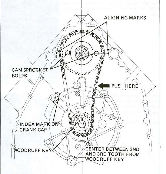
Once you have the engine set don’t move it anymore, and remove the two chain guides. The one on the left is held in place with one bolt, then the guide slides out. The right one (the adjuster) will come out once the adjuster screw is loosened out of the block and the assembly pulled off the mounting pins.
Below is a picture of the adjuster assembly removed to check for damage and wear. It was a newer type and had very little wear so I put it back.

You must now remove the two cam gear bolts and carefully pull the gear and chain off of the shaft. Now the fun part, you need to place the new chain on the cam gear (in your hand) and also on the crank gear. Now slide the cam gear on the shaft and see if the bolt holes line up (DON'T move the cam or crank shaft). If they don’t line up, you have the teeth off, so slide the cam gear off enough to see the holes and guess how many teeth you must move the chain. Keep doing this until the cam gear slides on the shaft and the bolt holes line up. Put the bolts in finger tight then check the alignment against the alignment diagram above to make sure neither shaft moved. If it’s all OK take one bolt out and put blue lock tight on it, then put it back, then do the same for the other and tighten both to spec. Put both guides back into place and make sure the adjuster assembly spring is connected properly. As shown below the chain fits a lot tighter. If you look at the tension adjusted bolt (the one that pokes through the rear case) you will see the slotted hole above the bolt (bolt sits at the very bottom of the adjustment slot). This is how it looks with a new chain (as opposed to the picture before where the slot was mostly on the bottom).

Below is a picture of the starter gear, which has a washer in front (shown), and one behind it (hidden). Make sure they are in the right spots if you have this come off. When I got the case off the shifter teeth plate popped out on me. You can also see where the shifter teethed parts have separated at the bottom of the picture. Will have to set that back together before the rear case goes on.

Well, now we need to put the rotor back on (along with the starter clutch gear) and lock tight the rotor bolt back in,
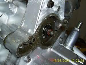
torqued to the required value. Once the rotor is back on and tight, we can move to the rear case and change the mechanical and oil seals (I left these for last so they wouldn’t get damaged). Before starting the seal install, make sure the case is clean, especially the seal hole and the small weep hole. The first seal to put in is the mechanical seal, as this one need to be press fit into the case. Using a section of threaded rod, some nuts, large washers and a 1” black pipe nipple, I fashioned my own “press fit” tool (pictured below).

Seeing my bike is an 82 custom, the rear case seems to have been made by Honda to fit a larger mechanical seal then the earlier models. The Yamaha seal I purchased was the perfect size. After cleaning the hole I placed the seal inside the start of the hole and passed the threaded rod through the middle of the seal, placing a large washer and nut on the inside of the rear case (washer big enough to prevent the rod from being pulled through the hole), On the front of the seal I slipped on the 1” pipe nipple (who’s outside diameter matched the seal lip diameter and inner diameter allowed the seal "innards" to fit inside it) and them placed a washer and nut on. Once the nuts are snugged up and the nipple is centered on the seal, you use a wrench to tighten up the nut at the front, which “presses” the seal into its seat. Go slowly and make sure the nipple is centered and square on the seal and the rod is centered in the hole through the seal. Continue tightening until the lip on the seal face sits flush with the case. Now, remove the press fit tool (nipple, nuts, washers and rod).
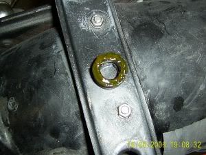
Once the mechanical seal is in, you will press a new oil seal into the inside of the rear case. Make sure the seal goes in until its lip is flush with the inside holes beveled edge, but NOT butting up against the back of the mechanical seal. When it’s in (can be pushed in by hand using the back end of an appropriate size socket) you should have a gap (1/4” to 1/8”) between the oil and mechanical seal. This is the space that the weep hole connects to. Use a flexible piece of stranded wire and poke it up the weep hole, and you should see it emerge between the two seals.
Below you can see the oil seal in the back case, and pushed in flush with the bevel on the case, with the open spring side towards the engine. You can also see the gap between the oil seal and mechanical seal. Hard to see in the picture, but there is a gap between the two seals, and neither seal covers the weep hole.

Here is a post from Shep's site on how to do a "engine in bike" mechanical seal replacement. Several hints and tips that are useful.
Cheap and Cheerful CX/GL500 Mechanical seal Replacement
Possible causes for a Failed job so please read.
Possible causes for a Failed job so please read.
1:Tearing the inner seal on removal from the new cup by not heating it up enough to release the old glue. 2:Not using enough or incorrect Sealant 3:Not orientating the inner seal correctly when fitting so it's grooves match the small flutes on the raised metal cup tube. 4:Not lubricating the Polo mint and Carbon face of the seal with some soap/oil
5:Turning the engine too soon after fitting the new seal.If possible leave overnight or a good hour or so before checking the engine can turn once the Water pump cover is back on.
6:Faulty or hard Copper crush washer(Re-anneal)
Note: If you use the Yamaha Seal(Part No:11H-12438-10-00) the glue they use is harder, so heat underneath the metal cup until it sizzles and be careful and don't force it. 
Note the 10mm thrust washer painted red here .Sometimes, due to age, it's welded to the cam shaft and it is difficult to see.
Important! It MUST be there and also if it is there you do NOT want to place another one on top of it!!!
1:Place washing up bowl under Radiator. 2:Drop Coolant 3:Remove Radiator if you wish. 4:Turn Cooling fan to access and remove the Left and Right 10mm cylinder Jacket bleed bolts and allow to drain into washing bowl.Replace bolts after draining now!!!!(Requires 10mm socket with ratchet extension). 5:Remove cooling pipe.Note.Rubber o-ring on cooling pipe should be,"In-the Groove".Use cheap silicone sealer on re-fit. Silicone Sealer 6:Remove Seat and tank. 7:Remove Large rear Engine Hanger/Frame bolt. 8:Remove the two smaller rear hanger bracket bolts and slack off the front rear hanger bolt so you can swing the Bracket along with the coils up and out of the way. 9:Remove Carb inlet bolts and slack off the inlet boot locking rings etc so you can maneuver the carbs out of the way and rest them on top of the frame. 10:Remove the Water pump cover bolts and pull the Small rubber pipe off the back of the Water pump cover. 11:Prise off the Water pump cover. 12:Remove impeller taking note of the 10mm thrust washer that,"MUST" be on the end of the Cam-shaft when you re-fit the assembly and the copper,"Crush" washer that goes beneath the 10mm domed nut that holds the impeller on 13:Pull off any way you can the Synthetic Spring loaded rubber boot.This is the part of the system that most commonly fails and cause the weeping coolant leak. 14:With a small blunt screwdriver clean the area inside the metal cup of debris.Brake/Carb cleaner should be at hand as it's the best for de-greasing/cleaning and use liberally inside the up and dry off with tissue(I use toilet roll). 15:Remove the spring loaded Boot part from a new Mech Seal.This should be done carefully so as not to tear the boot.If you apply a little pressure to the boot to try and force it out whilst playing some heat to the under side of the metal cup(I used my cigarette lighter)this softens the sealant they use to bond the boot to the cup and it should come free. 16:Smear a medium amount of silicone gasket sealer onto the bottom of the Rubber boot.
17:Insert boot into cup taking into account the protruding Metal lugs of the Metal part of the Mechanical seal e.g orientate correctly when fitting the boot.
18:Press new boot a few times into the cup to make sure it compresses and releases freely around the lugs.
You can now re-assemble the water pump as normal.Smear some washing up liquid on the Ceramic Washer(Polo Mint) before you do and push a pin through the weep hole to make sure it's clear before you re-assemble.DON'T forget the 10mm THRUST WASHER that goes on the end of the cam-shaft!!!!! and the copper Crush Washer.
Update Note 1-20-13: It is now recommended that the copper washer be replaced, rather than annealed. The reason is that altho annealing restores the malleability (softness) of the washer, it does nothing to affect the thickness of the washer. A washer that has been previously installed may not allow the impelled to be firmly pushed onto the splines. A loose impeller will allow the splines to abrade and there may be a noise associated also. So, for the fifty cents, just order a new one!
Note:You can re-anneal the copper crush washer with heat using a blow torch or a gas cooker or similar.Heat until ,"Cherry Red" and let cool naturally,do NOT Quench!! This brings the metallic elasticity back to the washer
Extras:"Davy" are an Australian company who make irrigation pumps.Because of an obscure post I found on the Internet and contacting an Australian Guy called,"Buff7454" on an Australian Forum.He told me and sent me some of these Mechanical seals at around a 5th of the cost of what my local Honda dealer wanted!!
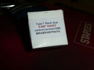
They are the same seals.There was no UK link/contact where I could get them."Davy" do supply them in Australia(of course) and from my research the USA.
Also these can be used,
Now that the rear case is done, it’s time to put the engine back together. Before you start, make sure you have put all parts back (the ones inside the engine like the drive shaft section) and make sure the shifter lever teeth are meshed properly. Check all yur little bags for any parts that got missed. You can see in the picture below how the teeth meet and how the small spring goes on. Once you’re happy you didn’t forget anything, do yourself a favor and get the shift peddle and slide it on the shifter shaft (bottom left). Make sure you can shift down into 1st, then up through all the other gears and back down. Do this a couple of times until your sure it works as it’s supposed to. You will have to be careful taking the shift peddle off, as the shifter shaft can and will pull forward and un-mesh the teeth.

Can't remember which way the gear on the end of the final shaft goes? Here is the answer, it is the bottom view.
.
Resized to 56% (was 800 x 447) - Click image to enlarge 
WHOA
Before you slide that rear cover back on, do this quick check of the pulsar coils. If they are reversed, the bike won't run, or run very poorly. He is a post from MurryF explaining how to check:
If you have the stator and pickups unbolted from the back cover, it is possible to reverse the way the pickups are bolted into the back cover and it goes like this (LOL) the pickups are marked R & L http://cx500forum.com/forum/attachments/technical-help-forum/8255d1392657238-spark-fuel-still-no-flame-help-me-somebody-l-r.jpg%7Cthumb%7C647x366px%7CName: L&R.jpg BUT THIS IS WHEN FACING THE FRONT OF THE BIKE so in other words when the cover is installed. When you remove the rear cover they look backwards just like the picture, BECAUSE YOUR ARE FACING THE BACK OF THE BIKE I have seen many times when people get their stators back from Gary or when they have had the motor apart, they forget how they came out, so they install the right on the right and the left on the left SO THEY NOW HAVE THEM BACKWARDS.
Once you are happy all is well, make sure your gasket surface is clean and then install the two locating dowels and the two large water passage dowels in to engine block. You can use a bit of grease to help hold them in place. Now, get some tape and cover over the splines on the cam shaft end and shifter shaft end, as this will prevent the splines from possibly damaging your new seals. Once that is done, place the gasket on the block using the locating pins to hold it (I also coat all my gaskets in clean engine oil, as it helps them stay put and makes them seal well (and in the future allows them to be taken off easier). Make sure to coat all the shafts with a bit of clean engine oil before sliding the rear case on to protect the shaft seals.
Now, take the rear case and have ONE MORE LOOK to make sure you are done in the engine and the shifter lever teeth are properly meshed (at bottom of picture above). Now careful slide the rear case on and push and/or lightly tap into place. Once it’s flush and on, check with a flashlight that the gasket stayed in place all around the engine, then tighten the bolts finger tight. Once all the bolts are in and you’re happy the gasket is in place well, get the shifter and shift up and down through the gears again. Better to find a problem now before getting the bike back together. Now, turn the engine through several revolution using the front engine bolt, and make sure there is no binding or rubbing. If it works fine, tighten the rear case bolts and check the gear shifting and engine spin one more time. Make sure the engine turns over like it did when it was stripped, only valve spring tension in spots when turning it. Below you can see the rear case back and a bit of the new stator visible.
Now, you can reinstall the advance unit making sure to line up the locating marks you made on it before removal. Once it is in and tight, slide the lobe piece back on and lock tight the bolt in. BE CAREFUL, I tightened mine too much and actually snapped the bolt. Fortunately I was able to get the broken bit out and install a new bolt. Use blue lock tight but make sure you torque it to spec. Now you can install a new gasket and put the case back on the advance unit.
Now time for the water pump install. Clean the mechanical seal face with solvent and do the same with the polo mint face, after which point DO NOT TOUCH EITHER FACES. Place the “special washer spacer” you removed back on after you have cleaned it well. Put a smear of liquid dish soap on the polo mint and seal faces you just cleaned with solvent, and place the polo mint on the water pump (cam) shaft up against the mechanical seal face. Avoid touching them again as any contamination of the faces will cause the seal to fail. The mint should slide right over the spacer washer (which fits inside it and aligns it with the shaft). Put the impeller on and with it sitting there (with all parts together touching), the threaded end should just reach the front of the impeller. Heat the copper washer up to nice hot red and set it aside to cool (annealing the washer). When it is cold, push the impeller in against the mechanical seal so you can get the washer on, then put a bit of Loctite blue on the thread and screw on the cap nut. Expect to have some pressure against the impeller from the mechanical seal spring, as that’s expected with a good seal. Tightened the impeller bolt and then spin the engine to make sure there is no rubbing, it should turn nice and smooth.
Install the two large water tubes and the two small locating dowels (can use a bit of grease to hold the in place), then the gasket, then the pump housing (again, I coat the o-ring and gasket in a film of oil) and put the two big bolts in. Install finger tight and spin the engine to check for any rubbing. If all is well, then install the small screws (I replaced them with stainless steel Allen head ones, and used a bit of copper anti-seize on the threads) and tightened them all up. Spin the engine again (with the 17mm crank bolt) and make sure it turns smooth with no binding or "rubbing noises" anywhere. Below shows the engine back together. At this time, just do a final confirmation the engine spins well (no pump rubbing noise), doesn’t bind and the shifter works up and down the gear range. Also, make sure you don't have any parts left over.

Now, all that is left is to remount the engine on the bike, add fluids and test it out. Before trying to start the bike, you will need to "prime" the oil pump and lube the pistons as the engine has been dry. Place a few drops of oil in each cylinder (leave plugs out for now) or spray some "lube" inside the cylinders. This will help lube the piston rings until the oil reaches them. Now, set the kill switch to kill any spark and turn the engine over with the starter in bursts of 3-5 seconds. You will notice the oil light will stay lit, and won't go out until the system primes and the pump can build up some pressure. After several starter bursts, you will eventually see the oil light go out during the cranking, indicating you now have a primed oil pump. You can crank a few more times to get oil around the engine, then install the plugs and actually start the bike. If everything went well you won't hear any nasty noises and it will start and run.
Your triple bypass is now complete, but you should now go and adjust the valves again followed by a cam chain adjustment (if you have a manual adjuster).
This site is backed by Number 85, who provide the hosting. If you need a website done, get in touch with them.
