Cleaning the Ignition Switch
The ignition switch on our bikes seem to be a source of problems after 30 years of neglect and use. Then one morning the lights don't come on, and the bike won't start. A little preventive maintenance would have prevented this. There are some differences between the CX and the GL ignition switches. I know the 83 GL's have an "accessory" position that the CX's do not have. But for cleaning, the basics are almost the same.
(Thanks to Dave F for the first pictures, and Reg for the later ones.)


The first step is to removal of the switch from the bike. Things are tight where the switch is located, but a 12" extension tipped with a 10 mm socket can be wormed up beside the lock barrel and engage the two bolts that hold the assembly to the triple tree. There is also a connector to remove at the bottom of the assembly that can either be removed before the bolts are removed (preferred), or after wiggling the barrel out of the wires. Use caution when undoing this connector, as there are multiple wires inside that can become loose or the locking clip can be broken.
Now take the assembly to the bench and lay it on a reasonably clean towel to keep the parts from hiding under the other junk on your bench. The bottom black end of the the assembly is held by 3 clips that are located in the bottom of the metal lock barrel. The key needs to be turned to a proper spot to be able to push these clips in. On the GL650, I know that it is the Accessory position. The CX's can be determined by trying different positions and attempting to push in on the plastic tabs.
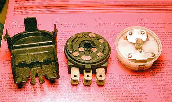
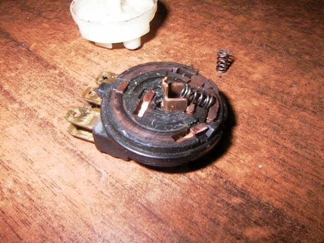
Carefully separate the assembly you have just removed. Inside you will find parts like (or very similar to) the ones shown below. In most cases, you will find corrosion, hard grease, and dirt. Using contact cleaner and a small brass brush or equivalent, cleal all the contacts that you can find. Pay particular attention to the white disk with the wipers. These are held into contact with the black base by little springs under the wipers. Make sure that the wipers will easily compress into the white assembly. I opened one recently and the prongs on the wipers were contacting the white plastic and would not allow for equal retraction. A bit of work with a razor knife trimmed the area so that it again worked fine.
Ignition Switch Insides and how it works.
Courtesy or Reg in Bristol. I would link to his site but it doesn't like links. (Fixed by Admin) http://www.reggiecx.uphero.com/teknix.html
Here are some pics of a Z/A/B(C?) ignition switch I stripped down when changing lock barrels.
Removing the black plastic cover, I found nasties on the blade terminals
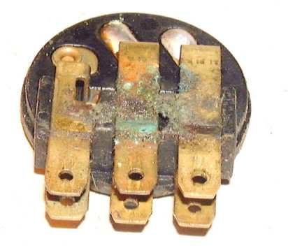
this corrosion with some nice dampness could lead to some interesting faults
The Switched Section The copper contacts and wipers were all in good condition and would be used again Heavy scoring, pitting and tracking would be suspect. DONT LOSE THE SPRINGS !! These little buggers have a habit of jumping out from under the two wipers so Be careful.
Heres what all the contacts do electrically
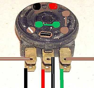
RED - Supply from main fuse GREEN - Earth/Ground via loom BLACK - Supply out when ignition is switched on BLACK/WHITE - Connected to ground when ignition is switched off. Linked to killswitch which does the same job. Stopping engine BROWN and BROWN/WHITE -lights/parking lights Check the wiring diagram for your model My wiring is home made and I dont use these connectors
When you have all the corrosion removed, apply dielectric grease to all moving parts inside the connector assembly. Before re-installing the connector, you may want to lube the actual key and lock assembly. Graphite is the preferred lube as it will not attract dirt and dust. Also lube the pin that locks the handlebars to the side position.
Now carefully install the lock assembly back into the triple tree. When you have the bolts secure, slip the electrical connector back on. You should be finished with this job for the next 25 years.
Text by Blue Fox
Here are some pictures of a GL switch. A bit different type of contacts, but the overall workings are the same.
This is a GL switch. I coated the removable contacts with solder (not shown).

Hold the white side down while prying off the black part, so you don't lose the small parts.
RustyTec ’81 GL500. Dallas Texas.
This site is backed by Number 85, who provide the hosting. If you need a website done, get in touch with them.
