Upgrade to a Electric Fan
Here is a detailed article on upgrading to a electric fan by Dave F. Thanks for the info, Dave.
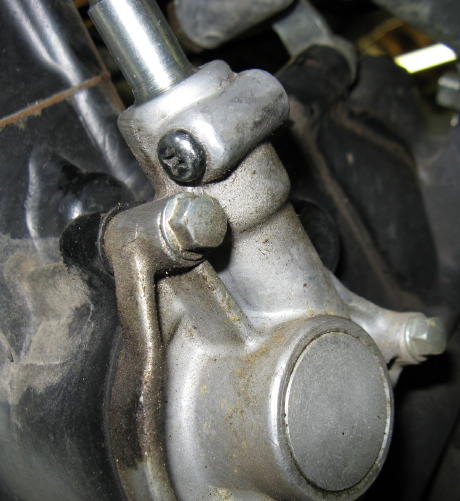
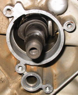
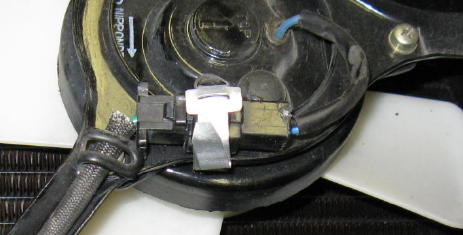
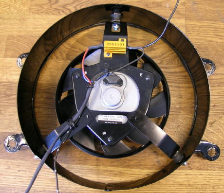
First, here is a picture of how the original fan is held on the cam shaft and how it is removed, and why a bolt rather than the front axle should be used to pop it off.
Thanks, Allan.
Resized to 72% (was 630 x 368) - Click image to enlarge 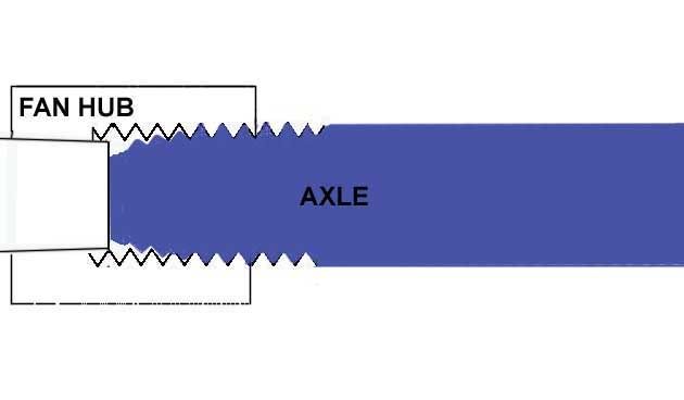
This diagram shows why the tapered front axle is not recommended for removing the fan,,a bolt will engage all the threads.
The large threads are the puller threads. There is no locking mechanism,,tightening the bolt should remove the fan. If you are using a proper bolt the fan should come off as you apply more torque on the bolt. They come off hard sometimes, be careful not to hammer on the fan as you may break the end off of the cam.
Here is a link to the thread that Dave F. started to share this information. I would suggest that it would be worth reviewing, in case there is some new information presented.
http://cx500forum.com/index.php?/topic/12958-electric-fan-upgrades-writeup/
CX/GL 500/650 Motorcycle Electric Fan Upgrade Information
- Revised 3-9-2012
- Introduction
All Honda CX/GL motorcycles have a liquid cooling system. When the bike is in motion at normal riding speeds, there is plenty of airflow through the radiator to prevent engine overheating. But when the bike is stopped or slowly moving, airflow through the radiator can be insufficient. To handle this situation, a fan mounted behind the radiator is used to pull air though the radiator. The non-turbo 500 bikes use a mechanical fan mounted directly to the camshaft. The turbo-500 and all 650 bikes use an electric fan. Both fan implementations were satisfactory back in the day, but with passing years several common problems have become evident. This write-up addresses those problems. Corrective actions taken for my own bikes are described in detail. My bikes are all GL's, but the recommended upgrades are also applicable to CX's. If you are considering similar cooling system upgrades, hopefully the information presented may give you some ideas and help answer questions that may arise. For the mechanical fan bikes, henceforth referred to simply as 500's for brevity, conversion to an electric fan is highly recommended, including usage of a fan power relay. A compelling justification for the electric fan conversion is presented. Factory electrical fan bikes, similarly referred to as 650's for brevity, also have room for improvement. My recommendations include installation of a fan power relay and replacing the radiator temperature switch with one that operates at a lower temperature.
- Acknowledgement
Special thanks and recognition are due to CX/GL Forum member Shep. In addition to his longstanding technical contributions to the forum, he was an early adopter and continues to be an advocate of electric fan conversions for the 500's. A significant portion of the information presented in this write-up owes its existence to his background research and advice. Shep also started and maintains the CX500 GL500 650 Global Forum.
- Wiring Tips and Suggestions
Prior to proceeding with any wiring modifications, a few minutes should be spent reviewing this brief Wiring Fabrication and Repairs write-up. It contains several tips and identifies sources for hard-to-find parts that may make the task easier.
- Electric Fan Conversion Justification
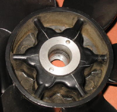
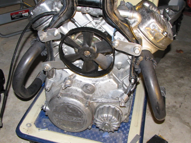
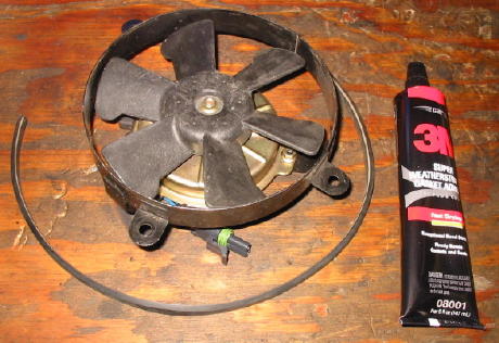
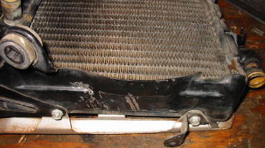
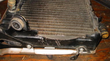
If your bike has a mechanical fan, you may be wondering why conversion to an electric fan is even worth considering. After all, it sounds like a lot of work and it's been fine for all these years, right? Electric fans have a number of advantages over the stock mechanical fans, improved efficiency being one that immediately comes to mind. But a compelling reason to upgrade is the tendency of the mechanical fans to develop stress cracks. When this happens the fan can come loose on its metal hub and make a lot of noise. It can also fly apart, destroying the radiator in the process. Several CX/GL Forum members have experienced this firsthand. Stress cracks are obvious in this original mechanical fan, now over thirty years old.
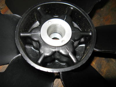
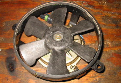
Unfortunately, new fans are also prone to stress cracks. The fan in this photo is only a few years old and has less than 500 miles on it; severe stress cracks are already evident. Judging from the original packaging, the fan was not old stock but had been recently manufactured. This is not an isolated instance, either, as several forum members have also reported stress cracks with new fans. Nor is it a case of improper installation, as this fan was carefully installed and torque values were adhered to in strict compliance with the factory service manual. Honda simply seems to have a quality issue with their replacement fans.
Often a mechanical fan will make a "tock-tock" sound after it has developed stress cracks. Even if you are not considering an electric fan upgrade it would be wise to check for stress cracks. When doing so it is important to inspect the rear of the fan, as the cracks are not usually visible from the front.
- Tachometer Cable Screw Replacement
The radiator must be removed to perform any of the electric fan upgrades discussed in this write-up. So this would be an ideal time to replace the tachometer cable screw while access is not a problem. Do it now and you may very well thank yourself later. In the event of a tachometer cable failure, the tachometer cable screw must be removed to replace the cable. Accessing this screw is difficult with the radiator in place. To make matters worse, the tachometer cable screw is usually tightly torqued from the factory and its head is easily stripped. Often when this happens the radiator must be removed to obtain better access to the screw. The original tachometer cable screw has a Philips head.
Here the tachometer cable screw has been replaced with an Allen head screw. In the event of a tachometer cable failure, the screw can now be easily removed with an Allen bit socket.
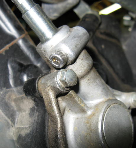
Note the screw can be installed from either side of the housing. At least for the GL bikes, it must be installed in the direction shown or subsequent access will be impossible without removing the radiator.
- Electric Fan Selection
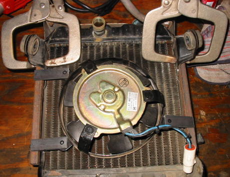
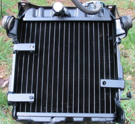
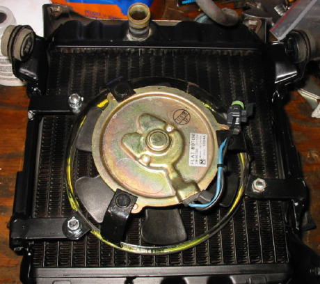
Electric fans specifically designed for use in motorcycle cooling systems are readily available at a reasonable cost. In particular, many high quality used fans from wrecked bikes are continually listed on eBay. My preference is the flat Ducati fan seen in the installation photos that follow. This fan has excellent airflow performance, a comparatively low electric current drain, and a physical size and shape that ease installation problems. It also has conveniently located mounting tabs and a built-in shroud.
- Mounting the Electric Fan
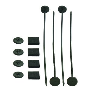
Several options exist for mounting the electric fan. Perhaps the simplest and least expensive method is to attach it directly to the radiator using a Fan Installation Kit. This kit mounts the fan to the radiator through the radiator fins using plastic rods and pads.
In this CX/GL forum thread, forum member Exploring/Carolina mounted a Ducati fan to the front engine hanger studs using some scrap .040" 6061T6 aircraft sheet metal. This setup is simple in concept and sturdy. Nicely done!
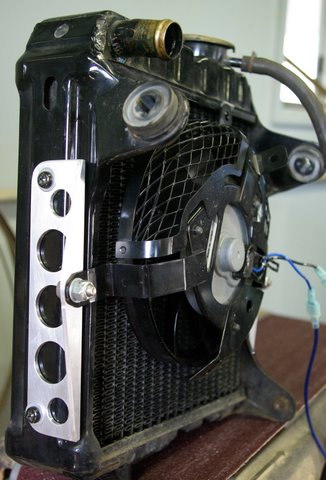
Others have mounted the fan to the radiator frame using metal brackets. This fine example is from forum member kureus.
Here is a very innovative approach. Forum member MGR1 mounted the fan to the original fan shroud using shock mounts.
My approach is described below. It was chosen based on what materials were already on hand - in this case some 1/2 inch square steel tubing and some flat 3/16 x 3/4 inch flat steel bar stock left over from previous projects. Like most folks, I chose to discard the original fan shroud. The rubber seal was removed from it and installed on the Ducati fan shroud using some weatherstrip adhesive.
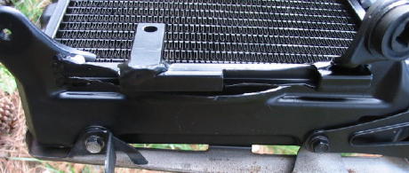
Both sides of the radiator frame were trimmed to provide clearance for the new brackets to be attached.
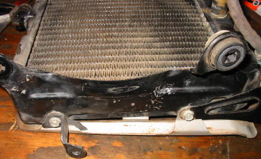
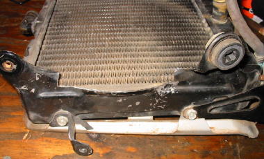
The Ducati fan was set into place on the radiator and the mounting brackets were mocked up and tack welded.
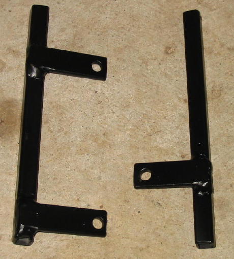
The brackets were then removed, welded properly, drilled, and painted.
Next, the brackets were welded to the radiator frame using the Ducati fan to guide final placement. Then test fitment of the radiator assembly on the bike and trimming the brackets was accomplished. After several iterations there were no clearance issues and a final coat of paint was applied.
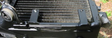
Finally the Ducati fan was bolted into place.
This mounting method is exceptionally sturdy and the fan is optimally placed. The fan can be easily replaced should that ever become necessary. However, if the radiator ever needs replacement there will be some work involved in cutting off the brackets and installing them on the new radiator. If that should happen on a road trip I'll probably just use an inexpensive fan installation kit as described above to keep going.
- Camshaft Clearance Considerations
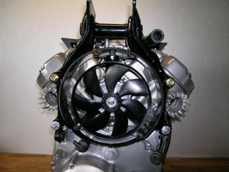
The original mechanical fan was mounted to the front of the camshaft. Accordingly, the camshaft protrudes from the front of the engine towards the radiator and consumes valuable space where the new electric fan could otherwise be located. One way of dealing with this interference issue is to mount the fan so it is offset from the camshaft, away from the center of the radiator. Alternately, the camshaft tip can be trimmed to provide additional clearance. Or a combination of both methods can be used. Forum member Exploring/Carolina illustrated this combined approach in the following two photos. First, the camshaft tip was cut so it barely extended beyond the camshaft holder seal.
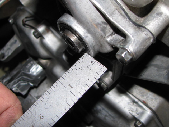
Mounting the fan slightly offset from center then provided plenty of clearance.
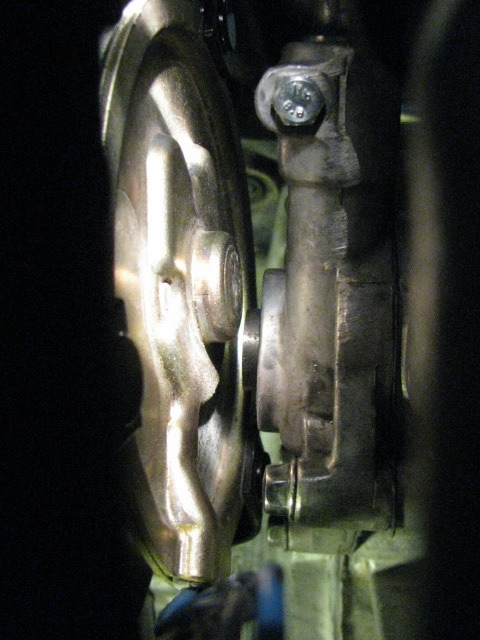
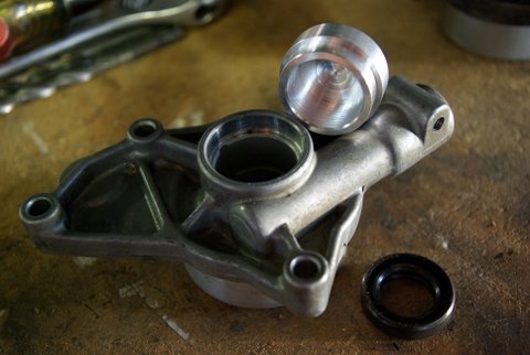
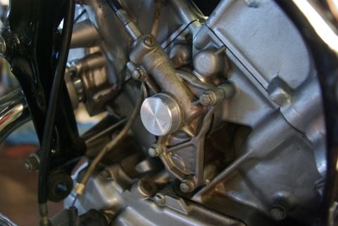
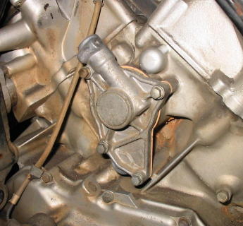
In this CX/GL forum thread, forum member kureus removed the seal and plugged the camshaft holder to prevent potential oil leaks as shown in the following two photos.
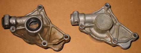
Alternately, a 650 front camshaft holder can be used if available. In these photos, camshaft holders from a 500 and a 650 are shown side by side.
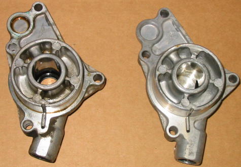
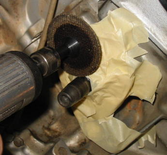
Installation requires the camshaft tip to be cut off even further. Care must be taken to ensure no metal filings end up inside the engine.
There is plenty of clearance if a 650 camshaft holder is used with a Ducati fan.

Disclaimer: After comparing the 500 and 650 camshaft housing dimensions I believe to be important, my conclusion is there are no problems with this swap. But there is always the possibility I may have missed something, so be aware there is an element of risk should you choose to proceed with it. So far my 500 seems to have no problems after the swap.
- Fan Power Relay
Based on personal observations and posts on the CX/GL Forum, ignition switch failures are relatively rare for 500's but not uncommon for 650's. Further, inspection of a handful of 650 ignition switches revealed they all had evidence of overheating and arcing of the contacts. The electrical loads of TI ignition 500 and 650 bikes are essentially the same except for the extra fan current of the 650's. In my opinion, this extra load is a major contibutor to 650 ignition switch failures. Accordingly, it is not unreasonable to expect similar problems with 500 ignition switches some time after conversion is made to an electric fan. An obvious solution to the problem is to use a relay to switch the fan power. If this is done, the relatively high current associated with the fan itself would not pass through the ignition switch or the radiator temperature switch. The only additional current passing through the either of these switches is that needed to operate the relay coil. The following two diagrams show the fan relay wiring for my GL500 and GL650 bikes. Note the close similarities between them.
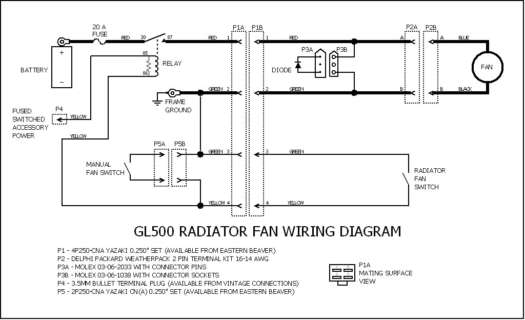
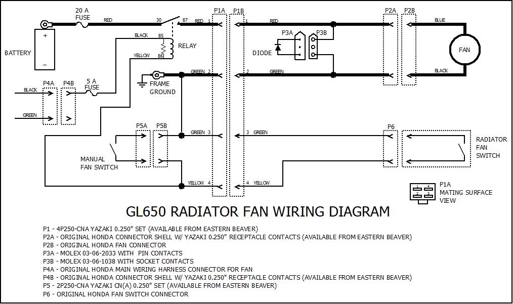
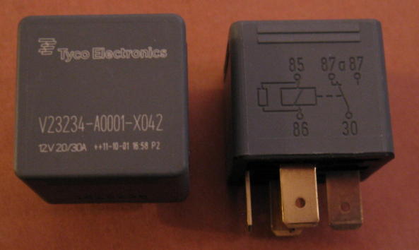
The wires denoted by heavy lines are 16 AWG, and the other wires are 18 AWG. The 20 Amp fuse is an automotive blade type fuse installed at the battery positive terminal. The fuse provides protection in the event of a severe overload or short to ground. Although not shown on the diagram, this fuse also feeds a high current accessory connector that can be used to power an air compressor or other external devices from the battery. Almost any automotive power relay could have been used, but I selected a relay that has an internal resistor connected across the coil. The risk of "tack-welding" the contacts is significantly reduced when a resistor is used for transient suppression, as is described in this TE Connectivity application note. My relay choice was the Tyco V23234-A0001-X042, sold by Waytek as item number 75414.
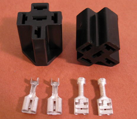
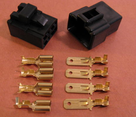
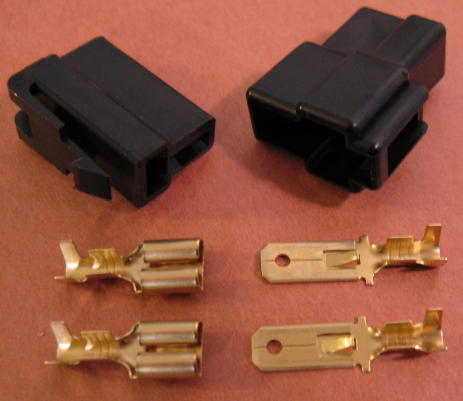
To make connections to the relay, a relay connector housing and contact terminals were used. These are Waytek item numbers 75281 and 31073, respectively.
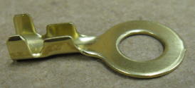
The frame ground terminal is the Eastern Beaver Products/Terminals/Open_Barrel/body_open_barrel.html#rings BLA-106 6mm brass ring terminal.
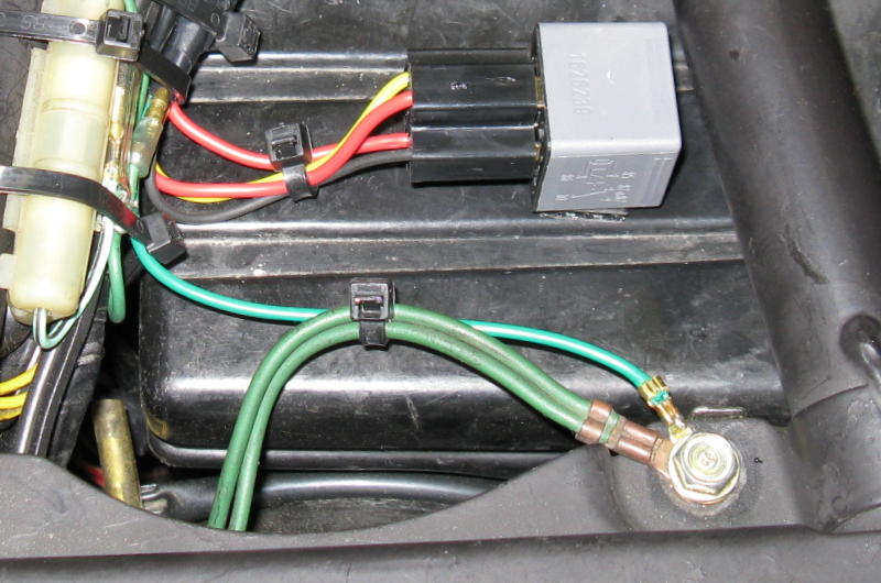
The relay was secured to the top of the airbox under the seat with industrial strength adhesive-backed Velcro. For good adhesion, both surfaces were cleaned with alcohol prior to installation. The ring ground terminal is visible in the lower right corner.
Connector P1 is the Yazaki 0.250 inch Products/Connectors/250_Connectors/250_connectors.html 4P250-CNA set from Eastern Beaver.
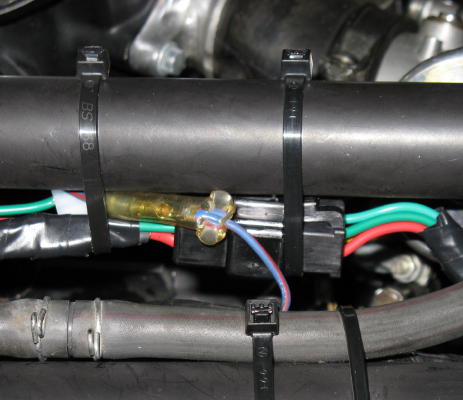
P1 provides for radiator and fan removal without the need to cut any wires. It was installed under the fuel tank, in front of the carburetors, on the right side.
For the 500, relay power was obtained from the accessory power connector located under the seat. This connector is fused at 5 Amps.
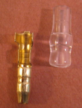
An SB2 3.5mm brass bullet terminal from Vintage Connections fits the accessory power connector perfectly.
For the 650, relay power was obtained from the connector in the main wiring harness that orignally powered the fan. This connector is only fused by the bike's main fuse, so a 5 Amp automotive blade fuse was added here (not shown.)
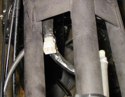
The mating connector shell from the original 650 radiator wire sub-harness was re-used. A new Products/Terminals/Open_Barrel/body_open_barrel.html#receptacles Yazaki 0.250 inch receptacle terminal from Eastern Beaver was installed in the connector shell.
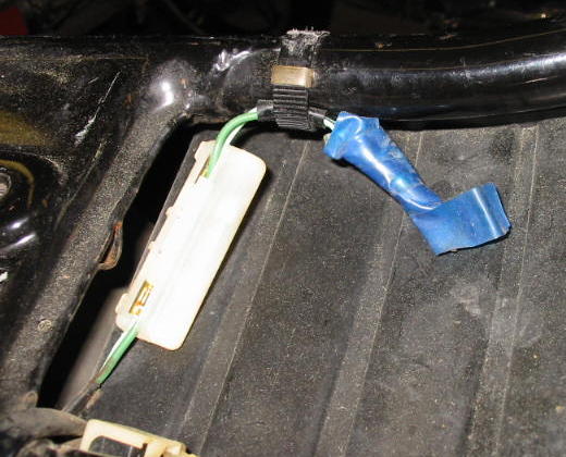
Connector P5 is the Yazaki 0.250 inch Products/Connectors/250_Connectors/250_connectors.html 2P250-CNA set from Eastern Beaver. It is used for connection to an optional switch to manually force the fan power on.
I chose not to install a manual switch at this time. However, connector half P5B was installed to make it easy to add a manual switch at a later date, if desired. It was installed under the fuel tank, in front of the carburetors, on the left side. A Snubber Diode was included to reduce voltage spikes that can result when the fan power is abruptly removed. I selected a 1N5819 Schottky diode from Digikey, although many other rectifier diodes will work fine, including the 1N540x series from Radio Shack. The diode was mounted to a Molex 03-06-2033 connector shell with 02-06-2103-C pin contacts, also from Digikey, and then covered with heat shrink tubing. The mating connector is a Molex 03-06-1038 with 02-06-1103-C socket contacts. This assembly was mounted adjacent to P1 under the fuel tank, as this location provides some protection from the elements.
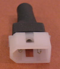
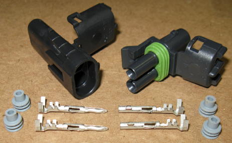
For the 500 fan conversion, a Delphi Packard Weatherpack connector was installed on the Ducati fan wire leads at P2.
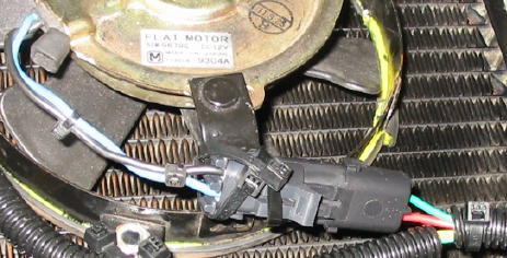
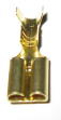
For connection to the 650 fan at P2, the original mating connector shell was re-used with new Products/Terminals/Open_Barrel/body_open_barrel.html#receptacles Yazaki 0.250 inch receptacle terminals installed.
Connections to the radiator temperature switch are discussed in the applicable Radiator Temperature Switch section.
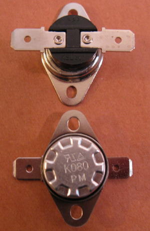
- 500 Radiator Temperature Switch
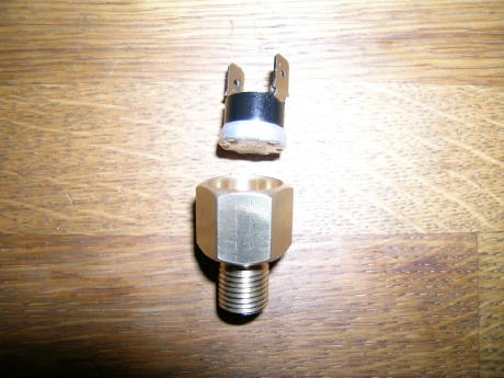
A radiator temperature switch is needed to control when the electric fan switches on and off. One switch commonly used in 500 electric fan conversions is a bi-metallic temperature switch like one shown in this photo. At the time of this writing, this switch is readily available on eBay; a search for the term "80C temperature switch" should return several hits. Sometimes the switch may be referred to as a KSD301 switch. The important features are that it have normally-open (NO) contacts and an operating temperature of 80C.
Ideally, the switch should be mounted on the bottom radiator tank. The mounting tabs and terminals can be carefully bent if needed.
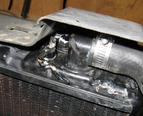
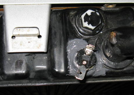
J-B Weld worked well for securing the temperature switch to the radiator.
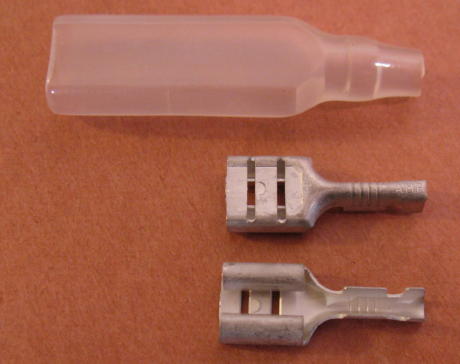
Amp Products/Terminals/Open_Barrel/ampopen_barrel.html 42640-2 Faston 0.250 receptacle terminals with dimples and matching plastic Products/Connectors/Sheaths/sheaths.html receptacle sheaths from Eastern Beaver were used to connect to the temperature switch.
The wires were routed in corrugated wire loom for support and protection.

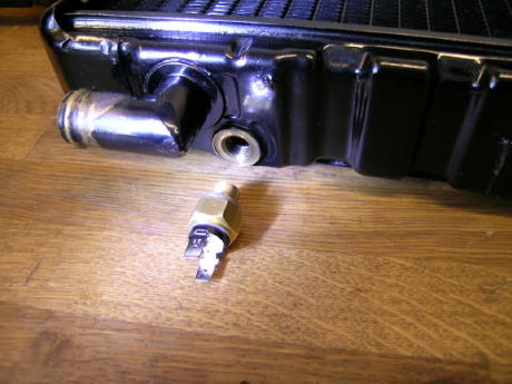
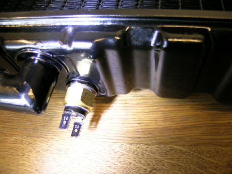
CX/GL Forum member MGR1 came up with a very nice way to mount the temperature sensor. He fabricated a brass plug with M12 x 1.25mm threads and a shallow hole cut in the top of it.
Next the sensor was glued into the plug, and then the assembly was installed in place of the standard radiator drain plug.
- 650 Radiator Temperature Switch
The 500's and the 650's use the same thermostat. So if the engine coolant temperature is being regulated by the thermostat then it makes sense that both bikes would have similar temperature gauge readings. In fact, this is the case when riding a 650 at speeds where there is plenty of airflow through the radiator. The temperature gauge typically remains just sightly to the right of mid-scale. The measured temperature is being held relatively constant by the thermostat as the 650's fan is not operating at all. Since cruising down the road is the bike's normal operating mode, if designed properly the engine should be operating at its optimum temperature. With insufficient airflow the temperature gauge display creeps upward and the fan eventually turns on. This happens somewhere around 3/4 to 7/8 of full scale, higher than most folks are comfortable with. Most likely the thermostat is wide open in this situation and is having no effect upon engine coolant temperature regulation. The system is running "open loop" as far as the thermostat is concerned. Lowering the temperature at which the fan turns on lowers the coolant temperature in the radiator. The goal is to lower the coolant temperature to the point where it is within a range that the thermostat can regulate. This can be accomplished by replacing the radiator temperature switch with one that turns on at a lower temperature. From this post on the VFRWorld forum, the following switches have a lower temperature range than the original Honda temperature switch, closing at 88.5C to 91.5C and opening at 82C to 88C:
Beck Arnley 201-0817
Borg Warner TFS500
Echlin FS-130 (NAPA Auto Parts)
Four Seasons 35934
Gates T274
Niehof WA-639B
Wells SW504
Good results have been reported with the Echlin FS-130 and the Borg Warner TFS500. Performance results of the other listed switches in a CX/GL application have not been verified to my knowledge, although they are also likely to be fine.
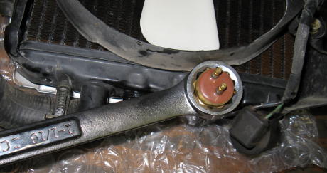
Replacing the 650 radiator thermal switch is a simple operation. First, the connector is unplugged from the switch.
Next, the switch is removed from the radiator. Caution - the lower radiator tank can be easily bent, particularly if a lever action is used to break the switch loose. Use of a wrench as shown in this photo is not a good idea.
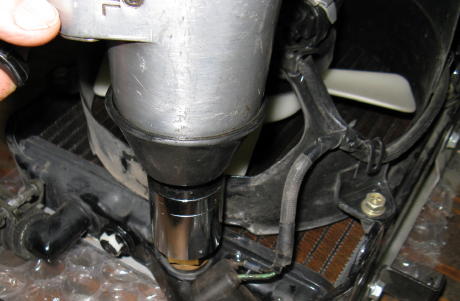
The risk of damage to the radiator tank is much lower if an impact wrench or similar tool is used to remove the switch, as the applied force is purely rotational.
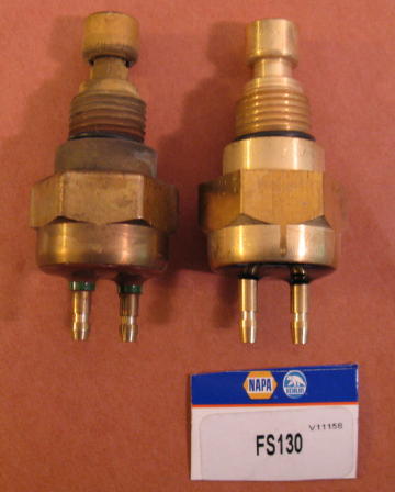
The original Honda switch and the Echlin replacement are compared side-by-side.
The replacement switch has been installed.
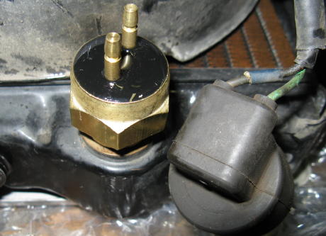
The original mating fan temperature switch connector, shown in the above photo, is referred to as P6 on the fan power relay wiring diagram. The connector wires were cut and spliced with longer wires to reach the P1B connector half.
- Fan Always-On Modification__
- Introduction
Another modification recently discussed on the CX/GL Forum is to have the fan always running when the ignition is switched on. When the fan is needed, it operates normally. But when it is not needed, the fan continues to run, but at a slow speed. A resistor is connected in series with the fan when it operates at slow speed. One benefit of this modification is a reduced surge current when the fan is switched on. Another benefit is the prevention of restricted airflow due to a non-running fan. I have not tried this modification yet, so I have no direct experience regarding these benefits. However, details are included here should you wish to perform the modification.
- Resistor Selection
The resistor value (measured in Ohms) determines how fast the fan runs; the fan will run slower as the resistance value is increased. There is no single resistor value that is appropriate for all fans. Its value is best determined experimentally by trying different values until the desired slow fan speed is obtained. Forum member MGR1 has found a resistor value of 15 Ohms works well with his installation, shown in this photo. The resistor is the gold-colored device secured to the top fan bracket.
In addition to the resistor's value in Ohms, its power rating must be considered. To determine the power dissipated by the resistor, the following formula can be used: P = V2 / R where P is the power dissipated in Watts, V is the voltage across the resistor, and R is the resistor value in Ohms. If a worst-case-possible voltage of 15 Volts is assumed as this is installed on a bike, the formula simplifies to P = 225 / R In this example, if a 15 Ohm resistor is used then its worst-case power dissipation is P = 225 / 15, or 15 Watts. MGR1 used a 25 Watt resistor, so his selection has a significant safety margin. Even though the resistor has a sufficient power rating, it may still get rather warm. Confined spaces such as under the seat may be a poor choice for the resistor mounting location. MGR1's selected location has plenty of airflow and is a good choice.
- Resistor Connections
The resistor should be wired across the contacts used to interrupt the current to the fan when it is switched off. If the fan power relay modification has been performed, the resisistor should be connected across relay terminals 30 and 87. If the fan power relay modification has not been performed, the resistor should be connected across the radiator thermal switch terminals.
This site is backed by Number 85, who provide the hosting. If you need a website done, get in touch with them.
