Troubleshooting your Turn Signals
Those darn turnsignals
Turn signals seem to be a constant topic on the forum. So let's see if we can take some of the mysteries out of the system and give a few tips on how to repair various items. While the system seems complex, if we take it one subsystem at a time, we should be able to fix most issues. All you really need is a multimeter, a couple of screwdrivers, some contact cleaner, dielectric grease, some sandpaper, and maybe a small wire brush.
There are several issues that seem to dominate the problems:
1. No lights anywhere, no indicators, no nothing. 2. Lights come on when signal is selected, but does not flash. 3. Rear lights come on, but fronts do not. (Or vice-verse) 4. Signals flash very slow (or very fast) 5. I have converted to LED bulbs and now they don't flash
Of course, all is for naught if there isn't any electricity reaching the system. So, take you multimeter, set it on DC voltage and probe both ends of the fuses at the handlebars. Make sure you ground one lead to the battery's negative terminal and use the other to touch the fuse ends with the ignition switch to ON. If you don't have 12 volts there, you will have to go to another article that hasn't been written yet.
The system can be broken into 3 basic areas: The signals themselves, the flasher can, and the selector switch. And of course the wires, but they seldom go bad. The signals are slightly different from front to rear. The fronts use a dual filament bulb (SAE #1073) that allows for the running lights to be separate from the signals. There are cases (I have one), where the rears also contained dual filament bulbs or sockets. Unless you can acquire some red lens for the rear, (very rare) these are illegal in the U.S. The normal rear bulb is SAE #1034. The flasher can is a simple bi-metallic switch that uses the current going to the bulbs to heat up a strip with a contact on the end. As the strip heats, it bends and opens the contact to the bulbs and when it cools a half second later, the current flows again to the bulbs. They also now have electronic versions that don't depend on amount of current flowing to operate. These use a small monkey inside to flip the switch, I think. The selector switch routes the current to the respective signals and their indicator bulbs.
The signal heads themselves can easily be a issue to the system not working. As they live in a hostile environment, moisture, dirt, and the occasional dropping of the bike tends to create problems. First, remove the lens of any suspected malfunctioning head and remove the bulb. I would test the bulb first. The easiest way is to touch one of the bottom terminals (front signal) to the battery positive, and use a short jumper from the battery negative to the bulb's case. The bulb should light for both bottom terminals. Conversely, the rear bulb has only one bottom terminal and use it in the same fashion. The bulb(s) are good? OK, then let's go to the next area.
Examine the inside of the socket that the bulb goes in. Is it nice and shinny, or rusty and corroded? Guess which one you want to see? Rust and corrosion can be removed with a round wire brush, sandpaper, and steel wool. Make sure the lights are off for this procedure. Clean everything up, including the bottom contact, and maybe spritz a quick shot of chrome paint on the socket. Cut a disk to mask the bottom terminal from the paint. Now try the bulbs again. Sometimes a slight crimping of the socket will help to make better contact. You can also use your multimeter to check for voltage at the socket. You should have 12 volts to both contacts (depending on where your selector switch is positioned). Measure from the bottom contact to the battery's negative post, and also to the socket's case. You should show the same voltage at both places. If not, there is likely a bad ground on this signal. This is fairly common as the grounds for the signals are usually inside the headlight bucket. And we know how crowded and tight things are in there. So check that out, especially if you have had the headlight out or messed with the wire bundles close to the head light. On the CX's, it is a simple matter to follow the wires inside the headlight to assure a tight connection. The CX's also use a spot welded tab inside the bucket for a ground. Insure that it is also hooked up. Bad grounds show up in more ways than the lights just don't work, there can be all sorts of weird conditions when the current is seeking a ground thru other paths. Before installing the bulbs, a dab of dielectric grease inside the sockets will forestall rusting and corrosion till the next bulb change.
Everything look OK inside the signal, but still not flashing? The flasher can makes the bulbs flash. It is located under the left side cover and is about 1-1/2" in diameter by 2" long, with two terminals on the bottom. If there isn't enough current flowing thru this, the bulbs will not flash, but may remain on. So if you have a rear bulb burnt out, the same side front will light, but not flash. Or if you switch to a LED bulb that doesn't use enough current to activate the flasher, the same will occur. These cans are available for several bucks at a automotive store, with the electronic versions (for use with LED bulbs) closer to ten bucks. If you think yours is bad, just replace it. By the way, the green wire hanging loose next to the flasher can is extra for 3 terminal flashers. It is simply a ground.
Here is a post from Jalet showing a electronic flasher & regular one:
If you put electronic flasher for led blinkers you usually need that extra ground. The stock flasher has two pins, but electronic flashers has three. For led blinkers you don't have to buy expensive special flasher. Just buy one of these cheap ones from ebay and they work fine. I have used them in couple of my bikes without problems. I have one in my CX500 now with led bulbs.
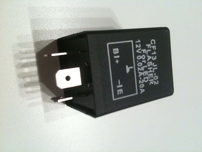
How to connect? B/+ --> cx black wire L --> cx gray wire E/- --> cx green wire or other earth
This is stock flasher.

The last area is the selector switch on the handlebars. Seldom do these actually break, more likely is that their contacts get dirty and fail to pass the current thru. A quick initial fix is to use the straw on a can of contact cleaner to blast into any openings in the switch. Then work the switch back and forth multiple times. It always works better to open up the clam-shell to find these areas, but sometimes a spray from the top and thru the bottom drain hole will work. If this doesn't solve the problem, you may have to remove the switch and open it up for cleaning. Be careful prying off the exterior selector button and also don't loose the small internal parts. Remove all old grease and then re lube with dielectric grease if you have opened the switch. If you have simply sprayed into the switch with contact cleaner, spray some silicone lube into the workings. This will allow for smoother action.
Here are a couple of pictures of the insides of the turn signal switch on the handlebar. Thanks, Sidewinder.
http://cx500forum.com/index.php?app=forums&module=forums§ion=findpost&pid=136964OneBadDaddy, on 31 December 2011 - 10:31 AM, said: Does anyone have a schematic of the inside of the left controls (79 CX500 C)? Tearing it apart will be easy, but I'd like to know its going back together the way it should.
This is the insides of a CX650, don't know if yours is like this or not.
Resized to 45% (was 1024 x 768) - Click image to enlarge 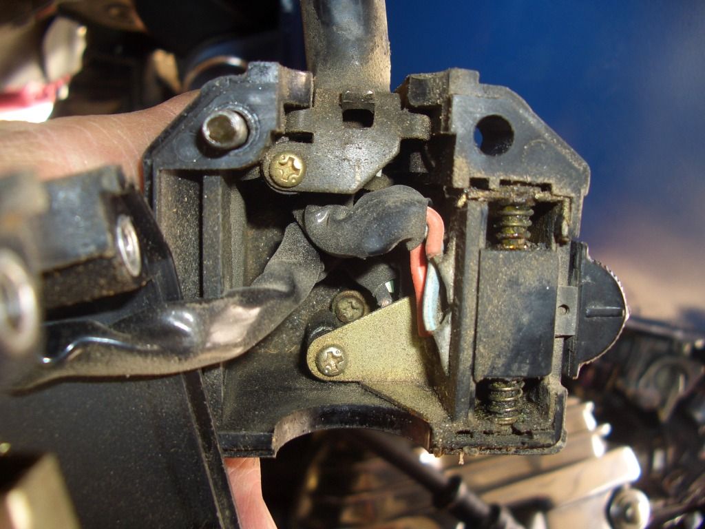
other half this is the horn.
Resized to 45% (was 1024 x 768) - Click image to enlarge 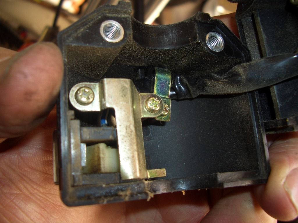
1983 CX650C
by Blue Fox
This site is backed by Number 85, who provide the hosting. If you need a website done, get in touch with them.
