Electric Fan
Electric Fan – FADM Stern GNSF
Converting from the standard mechanical fan that is bolted to the cam shaft to an electric fan as several advantages;
- Slightly less load on the engine as it doesn’t have to turn a fan.
- Old fan blades can crack and “grenade” through the radiator.
- Fan only runs when cooling is needed.
The actual job of doing an electric fan modification are straight forward, but can be done in many different way based on a persons preferences. While the method laid out here works well, it is by no means a cast in stone procedure. To perform this retrofit you will need to get some parts together based on how much you want to do with the work;
- Fan (needs to meet the listed criteria).
- Temperature switch (temperature setting based on position and preference).
- Manual switch (to manually turn fan on) (optional).
- Indicator light (to show when the fan is running) (optional).
The first thing you will need to do is get an electric fan that will work properly and will fit the tight space between the radiator and the front of the engine. There are a lot of motorcycle fans out there (Ebay etc) that can be used, but use care in choosing the one you want to install. Fan selection is important and must fit the following criteria;
- Size must be chosen so the fan will fit the space.
- The fans current draw must not be too high for the bikes electrical system.
- The fan must be capable of moving sufficient air through the radiator.
Size
It is best to measure your bike for the space you actually have, as it may vary with bike models. This retrofit was performed on a 1982 CX500 Custom, but the spaces should be very similar across all models. Because the radiator slopes down, and the engine front had “protrusions”, listing spaces would be too complicated. To be sure, check YOUR space.
Current draw
While all fans will draw a lot of current for the first few rotations (initial inrush to overcome the blades stationary inertia) until it gets up to operating speed. Try to get a fan that has a listed current draw (draw when the fan is running at its operating speed) at 2 AMPS or less. Some motorcycle fans can draw as much as 8 AMPS when running and these ones will put a huge strain on the bikes stator.
Air movement
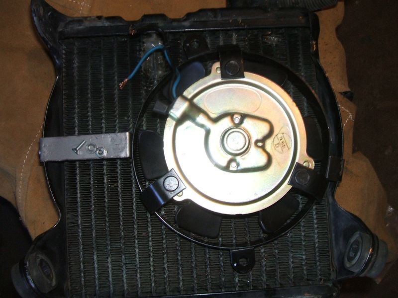
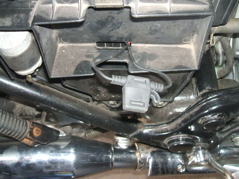
Most motorcycle cooling fans will move sufficient air to usefully cool the bike, but other types of fans can also be used (computer fans have been used). The goal is to find something with a high CFM (cubic foot per minute) rating as possible, while still keeping the size and current draw low. The fan used in this retrofit was a Ducati radiator fan # 748 916 996, but any similar fan would work as well. While I had no specs on this fan, testing it when it arrived showed it would draw 1.85 AMPS when running. The fan is shown in the small pictures below (sorry, thats the only size pics I have).
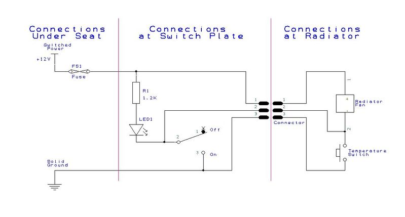
This mod can be done with the engine on the bike (I did mine engine out as I was doing other repairs), but you will need to drain and remove the radiator. While it is conceivable you could do the work with the radiator on the engine and just pulled forward, the increased dificulties in performing the steps might make it pointless to try. Draining and removing the radiator is really very simple and fast, plus gives you a chance to clean it up a bit. Below is a wiring diagram for the retrofit I did, which allows the fan to be manually controled and always shows if the fan is running or not.
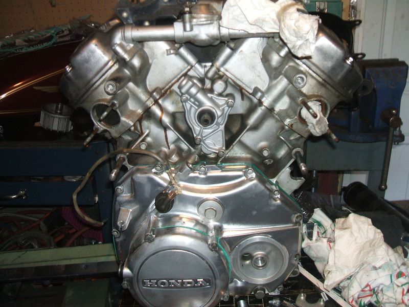
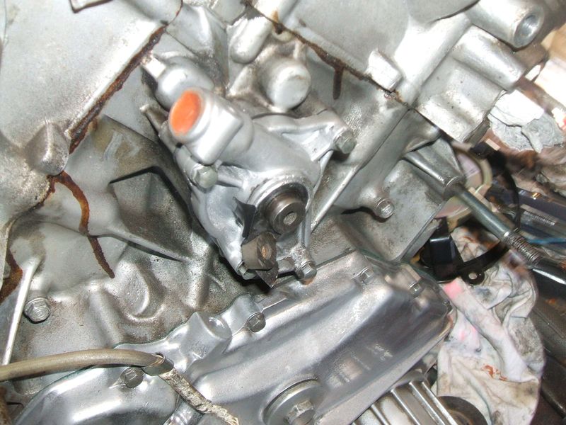
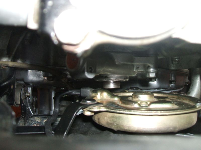
 Once you have the radiator and fan shroud (a metal ring that circles around the outside of the fan blades) off, the first thing to do is remove the existing mechanical fan from the cam shaft. This done by removing the bolt that holds on the fan (passes through the fan hub and screws into the cam shaft, and then inserting a "puller bolt" (M14 1.5 pitch X 2") which will screw into the fan hub and but against the cam shaft. As you tighten this bolt, it will push against the cam shaft end and force the fan forward and off the tapered shaft. If it doesnt want to come of right away, tap the head of the bolt with a hammer (tap, not smash), then tighten the bolt a bit more. Keep doing this until the fan comes off. You will not be able to see the front of the engine and the space you have to work with (as shown below).
Now its time to determine WHERE you are going to mount the fan and HOW. Where will be based on the pace between the radiator and the engine, and the type of fan you have. Some have had to trim a bit off the cam shaft while others have been able to do the installation without touching the cam shaft. The hardest part of the actual work is determining your fan location.
To do this it is best to temporarily mount the fan on the radiator with some form of “non permanent” mounting, like duct tape. This allows you to see what locations work and which ones don’t. So, tape the fan in a starting location and install the radiator and fan on the bike. You don’t need to bolt it up, just place it back on and check your clearances. Keep in mind for now if the cam shaft seems to be in your way, you CAN remove some of it if you want. On this retrofit, I removed about ½” off the cam shaft, as I had no intention of ever going back to a mechanical fan, but up to a ¼” can be removed and the old fan will STILL go on. Also, most people that do this retrofit remove and discard the “fan shroud” that normally sits around the fan, as it gives more space and the electric fans already come with a shroud as part of the fan.
Once you have the fan placed where you want to mount it, carefully remove the radiator and fan. Now that you know WHERE you want it mounted, you will need to figure out HOW. Since the location I found to mount the fan allowed one of the mounting ears to screw directly to the radiator, I decided to fabricate a stiff metal mounting bracket for the other side to span the radiator and have two stiff mounting points.
Since the radiator on this bike has “curved” metal forms on the sides, I used these as the mounting point. The main reason is I wanted to stay away from any area where drilling could damage the cores or top and bottom housings. I bent one mounting ear on the fan 90 to be able to mount to one of the side sections. Drill a hole it the curved radiator piece and use a nut and bolt to mount it. I then fabricated a mounting bracket out of steel (used a stiff 18 AWG steel so it would be very strong and not flex). I put bends in both ends so I could mount one end to the fan shroud (since the ears are not opposite each other) and the other to the curved section of the rad.
When done, I test fit the fan and radiator on the bike to make sure it fit with no issues. Since I had a section of radiator core that had to be repaired (due to a flying fan bolt) I wanted my fan mounted above the repair where space was a bit tighter (cam shaft was in the way). At this point I decided to lop a bit off the cam shaft to make sure I had a lot of clearance. You can see below the section I cut (hung on with some tape) off the cam shaft, which is actually very soft and easy to cut.
 Below is an picture of the space between the fan and engine taken from above. The cam shaft actually sits below the fans protruded wire housing section and gives me well over 1/2" clearance between it and the fan casing.
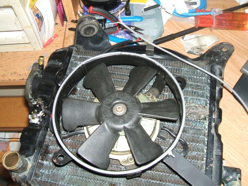
 Now that I had the mounting done, I removed the radiator and fan so I could wire it up and add the temperature switch. During the process, I got a question posed to me on the forum about the fan contacting the radiator and maybe rubbing. While the fan DID sit right on the radiator, the stiff mounting did prevent any movement. Even so, I decided to put a “cushion” between the two just in case. What I ended up doing was stripping a section of security wire and using the outside insulation jacket as a “gasket). Once stripped off the cable, I slit it right down its length and cut it to size. I then slid it over the fan lip all the way around and crazy glued it into place. Now there is a flexible cushion between the two metal parts (I did this part after I finished the radiator wiring).
The next step is to mount the temperature switch. With others doing this retrofit, some installed it on the top of the radiator, others on the bottom. Installation location seems to be a personal preference but does effect the switches operation as follows; With the switch mounted on the top, the switch will see the coolant at the temperature it leaves the engine and enters the radiator, while mounted on the bottom it will see the coolant that has already gone though the radiator fins, which will be a lower temperature. Either spot will work, but will require you to pick a temperature switch value based on “when you want the fan to come on”. I didn’t really have a choice as there is really no room to mount a switch on the bottom of my rad. While I could have mounted it to the ‘underside” of the radiator bottom, I really didn’t want wires hanging down there.
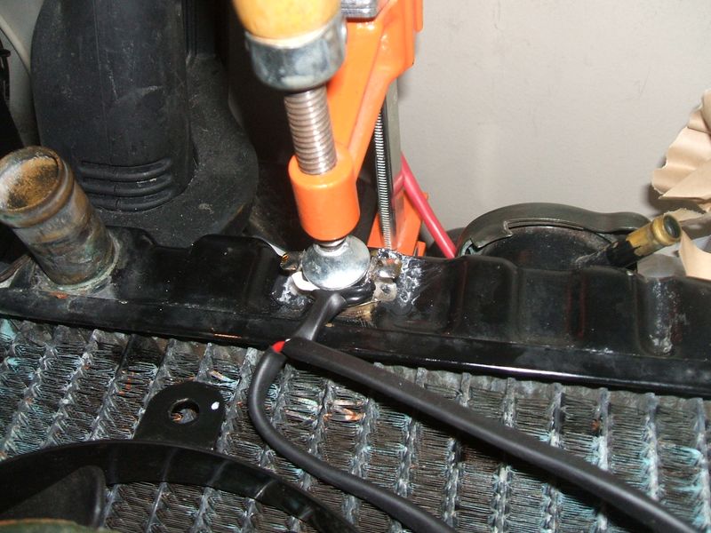
So, to mount the temperature switch to the radiator (top in my case), I used glue. It’s the easiest and most “non intrusive” way to mount it. As for the type of glue, anything that will stick it AND keep it stuck there is fine. I used crazy glue (loctite 401) to stick it on after removing the paint from that section of the radiator. I used a large clamp to keep in pressed in place until I was SURE the glue was dry (left it overnight). I then used gelled crazy glue (loctite 454) around it for extra hold.
Now, having worked in electronics for many years, I am anal about wires dangling, so when it came to wiring up the fan and switch I used heat shrink tubing to keep it neat, plus it adds a great deal of “stiffness” to the wires to allow them to be “formed” into place. I also chose to use connectors so that I would be able to easily remove the radiator in the future without cutting wires. In my case I reused my old stator plug set after cleaning up the connector and pins. Once the wires were soldered in place on the temperature switch, I coated all the exposed metal contacts and wires with an insulation coating (conformal coating used on PC boards) to keep the connection water tight and corrosion free. You should do this with what ever "insulating/waterproofing" coating you want to use.
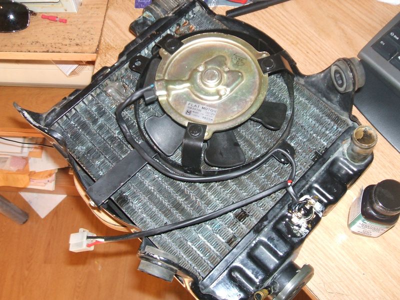
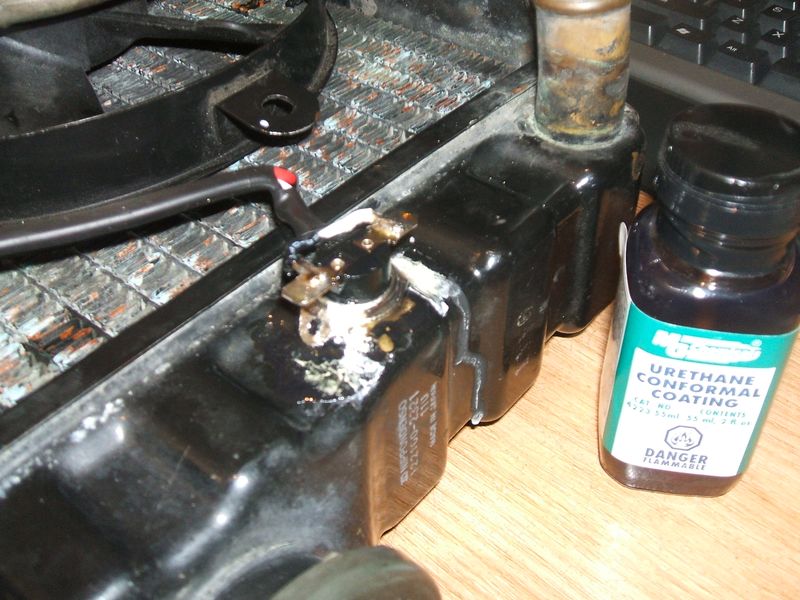 With the fan now mounted securely to the radiator and wired up (to the connector), I formed my wiring to a neat curve and made sure it would not move around. Below shows a pic of the finished unit ready to put back on the bike.
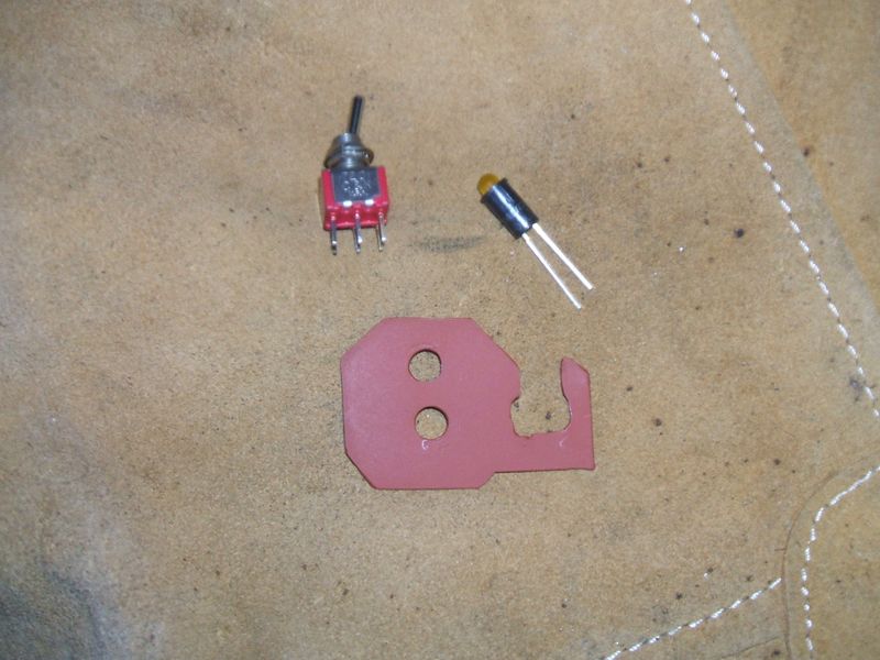
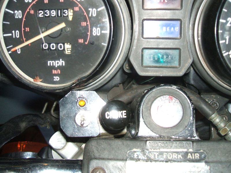
Now, it was time for me work on the power feed for it. Since I like the idea of a manual switch and indicator (would highly recommend it to anyone putting an electrical fan on, just in case the temperature switch falls off or fails) I started looking for a place to mount it. The best place I found was next to the choke lever, which made it easy to reach and look at. To mount it I created a mounting bracket that would use the chock handle assembly itself as a mounting point. By making a bracket with a similar cross section opening as the choke handle assembly, I was able to slide the bracket under the choke handle assembly and use its nut to secure it. After a few test fits to make sure I was happy with it, I priming and painting the mounting bracket. (shown here below after the primer coat with the switch and light).
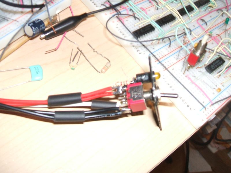
With the mounting bracket done, it was time to mount the parts and wire it up. I chose the switch and LED as I had lots on hand an from electronic work, plus LEDS are small and last a very long time. I used the "encased" LED as they are easy to mount (just push in the hole and a bit of glue). I used the switch terminals to wire everything up neatly (used some unused terminals on the switches second contact set as a join point) and compactly, as well as a way of "holding" the limit resistor so it wasnt "in line" with the wire (with the resistor holding the wire on it creates stress and can easily break). Below is what it looked like when all soldered up.
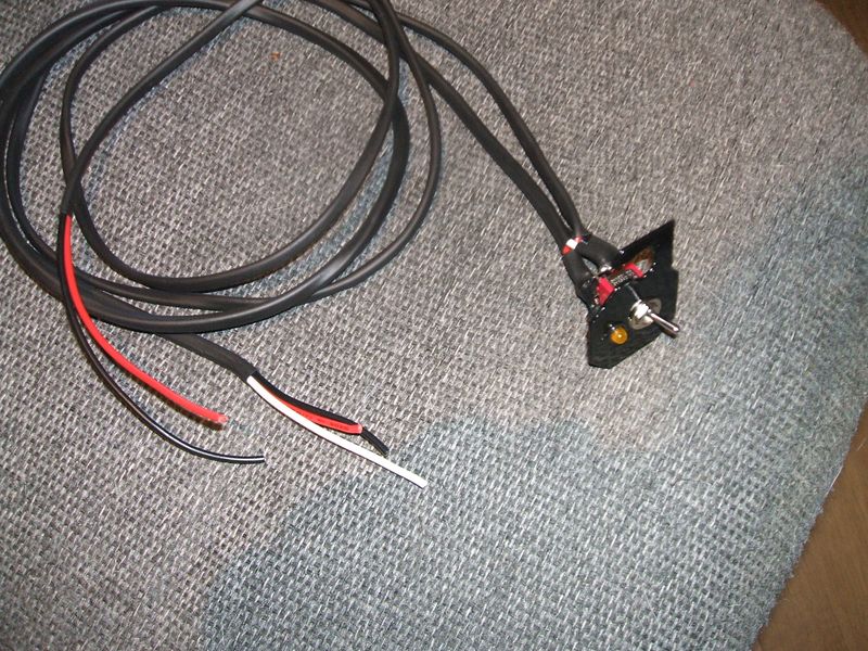
And again with the heat shrink in place and set to insulate the connections as much as possible. One cable set (black and red) run to under the seat and supply power for the fan, the other (black, red and white) goes to the connector that mates with the fan connector.
I tied the ground to the same point at the battery ground to make sure I had a good ground for the fan. I located an “accessory” inline fuse under the seat (not being used for anything) and used that wire from the harness to feed a new “plug in” fuse holder that I have mounted under the right side cover (where the tool kit I have goes).
All connections and slices under the seat were soldered and covered with heat shrink. The switch assembly was then mounted to the choke handle assembly and the fan line was connected to the mating plug (old stator one) to connect it all up to the fan and radiator wiring. Below is the switch assembly mounted to the bike.
With the bike all back together and the collant back it, I put the bike through its paces. I found that the fan comes on when the temp gauge gets to its center possition (just past the thin/thick line junction) and turns of when the temp drops to the start of the fat white line. I am very pleased with the performance of this fan and very glad I did it.
This site is backed by Number 85, who provide the hosting. If you need a website done, get in touch with them.
