Temperature gauge
Temperature guage
The temperature guage is incorporated as part of the tachometer head in most CX & GL models. Even the model that use a different layout, the basic working of the guage is the same. The basic principle is that of a resistance check on a analog multimeter. A needle is swung by a magnet to correspond to the changes in the resistance of the sender unit in the thermostat housing. A voltage regulator is used to maintain a 7 volt potential to ground from the meter. There is a very good reason for doing this, it isn't just a engineer's study. The normal voltage in the bikes harness will range from a low of approximately 11 volts during a crank or low battery, to almost 15 volts at high RPM. Since the electromagnet in the guage assembly needs a constant input reference, a voltage regulator is used to provide this constant 7 volts during operation.
Since this is a simple system, there are not many parts to go bad. The sending unit in the thermostat housing seldom has problems, but it can be checked with a multimeter set to measure resistance. Measure the unit cold, then when warming up. The resistance should change as the unit warms. If it does, consider it OK. The needle assembly in the tach head is also very durable. There just isn't much to go bad there unless there are unusual circumstances such as water immersion.
The voltage regulator does cause problems tho. If the regulator fails and provides 12 volts, the needle will register HOT-HOT. If the regulator doesn't provide any, or extremely low voltage, the needle will register low, or no movement. The check for this is simple. The voltage regulator is a cubed shaped unit about the size of the end of your thumb. It sometimes is in a rubber holder under the speedometer, sometimes inside the headlight bucket. Three wires will come out of this, a green, a yellow, and a black. The black is 12 volt input, the green is ground, and the yellow is 7 volt output to the guage. So, with the wires still attached, except for the yellow, measure the voltage from the yellow to a good ground. If you show 7 volts, you can consider the unit good.
If you find the unit to be defective, a new one can be constructed from Radio Shack parts for less than $5.00. Thanks to Reg in Bristol for the following directions.
by Blue Fox
Link to a thread on the CX/GL forum [Temperature? What is Normal]
Home made 7v Regulator(Courtesy of Reg )+ Test
by Admin » Tue May 05, 2009 3:27 pm
Note:If the bracket on top of the thermostat that screws into the engine(not the two bolts that hold the thermostat top) is loose or not grounding correctly you will get a,"High" reading on the Temp gauge.
Quick test
1:Set Multimeter to 20v DC range.
2:Open the green/blue leads connector to the rear of the thermostat under the tank and measure the voltage form the gauge when the ignition is on to the frame/ground.
It should be around 6.75v to 7v DC
If this is ok suspect the sender unit itself which is housed in the the thermostat housing.
Home-made
Alternative 7V Voltage Regulator
Warning!!!.Only use 5mm Green LEDs.Not any other size.
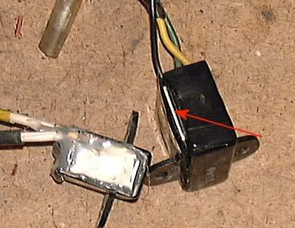
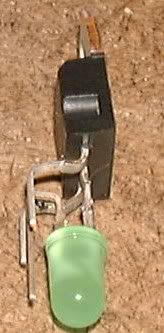
The 7v regulator is used to give a steady power supply to the Temp and Fuel gauges. They can often give a high output when failing and overdrive the gauges This can get you pulling the cooling system apart before you realise you have a fault in the Regulator I find the easiest way to check the output is to take a reading on the bullet connector to the rear of the thermostat with the ignition on. It can be done with the tank on but its no big deal to remove the tank on a ZAB type CX. In the pic below is a failed regulator. The red arrow points to a split in the casing due to overheating. The other one has my DIY version fitted into an original case. I usually try and use the original leads too. but in this case they had been chopped off.
I have had a couple of these on extended test for quite a while now with no problems reported.
Component cost is about £1 Here's the circuit
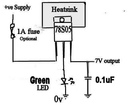
Crude maybe,but effective and pretty damn reliable too the fuse is optional and so is the 0.1uf cap on the output.
HOW IT WORKS
The chip controls the output voltage with reference to ground. So, what we do is bump up the ground by putting a green led between the 0V pin and ground. This usually gives around 6.95V. That's near near enough. A red LED will give about a 6.5V output, yellow 6.75V so use green OK? The heat sink is essential ! The chip has to dissipate heat and a heat sink will allow it to do that without damage The output cap is non essential, its a crude circuit and minor fluctuations will go unnoticed. I've never bothered to fit them. The 7805 IC is common as muck and cheap too. It is rated at 1 amp and the 78S05 2 amps. If I wanted to drive two gauges I'd use the 78S05.
Assembly tips:
The 7805:
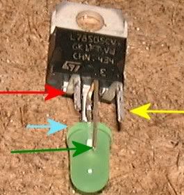
When laid on its back the pins are from left to right
Input (red)- Ground (green) - Output (yellow) The input connects to ignition live which on the CX is a black cable
The Ground has the green led between itself and ground
Output goes to the temp gauge
............
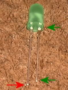
The green LED The longer leg is the anode or positive leg (red arrow). this is the leg that must attach to the centre pin of the 7805. the shorter leg is the cathode (green arrow). this is usually denoted by a flat on the clear body as well. this leg connects to ground.
Soldering: Don't overheat the 7805 or LED ! this may damage/ruin them. Tin the cable ends and legs with solder then the briefest touch with the iron should attach them to the 7805 and LED
I use heat transfer compound when fixing the 7805 to the alloy heat sink with a small nut and bolt or pop/blind rivet. I also test it before potting the circuit in epoxy or hot melt glue
Here's a pic of one on my bench I try to keep them as compact as possible so I can fit them into the original cases and have as large a heat sink as possible
If you use a different method, be warned that if the heat sink shorts to ground, the output will drop to 5V as this will in effect bypass the LED and it will behave like a normal 7805.
Insulator kits are available for this type of IC and cheap too should you want to use them
This site is backed by Number 85, who provide the hosting. If you need a website done, get in touch with them.
