Switches
Contents
- 1 There are many switches used on the CX and GL series of bikes. We will try to explore their function and how to repair or replace them if needed. The switches will be reviewed starting with the Starting Switch, Kill Switch, Horn Switch, Turn Signal Switch, High Beam Switch, Clutch Switch, Brakes Switches, and Ignition Switch. We will also look at the Starting Solenoid, as it can also be considered a switch.
- 2 Starting Switch:
- 3 Kill Switch:
- 4 Horn Switch:
- 5 Turn Signal Switch:
- 6 High Beam Switch:
- 7 Clutch Switch:
- 8 Brake Switches:
- 9 Ignition Switch:
- 10 Starting Solenoid:
- 11 Restoring the switch's appearance:
There are many switches used on the CX and GL series of bikes. We will try to explore their function and how to repair or replace them if needed. The switches will be reviewed starting with the Starting Switch, Kill Switch, Horn Switch, Turn Signal Switch, High Beam Switch, Clutch Switch, Brakes Switches, and Ignition Switch. We will also look at the Starting Solenoid, as it can also be considered a switch.
Starting Switch:
The push button switch on the right handlebar that used to start the bike is actually a dual purpose unit. One function is to send power to the solenoid to turn the starting motor, and the other function is to drop the headlight out of the circuit while the bike is cranking. This allows for more voltage to be available for the starting process. Here is more information on removing and cleaning the Starting switch: Rebuilding the Starting switch
Kill Switch:
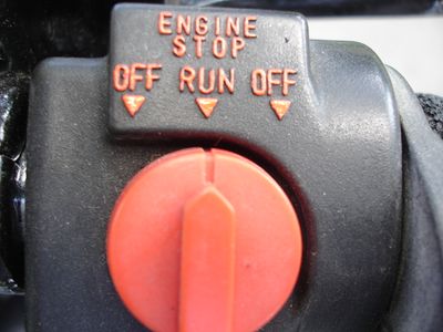
The kill switch is one of the simplest switches on our bikes. It is just a contact/no contact style mounted on the right handlebar. While its function is the same on our bikes, the actual operation is different on the CDI vs the TI (transistorized) style ignitions. This switch is simple to remove and clean up if necessary also.
On the CDI style bikes, (1978 - 1981 CX's), the kill switch grounds the black w/white strip wire that comes from the CDI box. In fact, you can check the operation of the switch by unplugging the connector at the CDI, and then note if the bike continues to run. Then ground the CDI wire with a appropriate lead and see if the bike stops. Or measure the continuity from the blackw/white stripe wire going to the switch at the CDI and note if the continuity to ground is interrupted as you work the switch.
The kill switch on a TI bike (All GL and 1982 & 83 CX's) use a different method for the kill switch. Since the TI bikes rely on battery power instead of stator windings to power the ignition, the TI bikes interrupt the 12 volts coming from the ignition switch to stop the engine. So, in a properly operating TI system, the blackw/white stripe wire going to the sparkers will have a 12 volt potential to ground when the ignition and kill switch is "ON". When turned off, the current is prevented from flowing to the sparkers.
This also means that a kill switch from a CX model (normally open), does not directly exchange for one used on a TI model (normally closed). It may be possible to change the contacts internally to allow for these to interchange, I seem to recall having done this several years ago, but can't remember the details. I do recall that removing the kill switch knob entails slipping off the very small circlip on the under side of the knob shaft and very carefully allowing the ball and spring to drop to the floor, never to be seen again. A clean towel under and slow release of the knob would be prudent.
Horn Switch:
The horn switch is also a simple pushbutton type mounted on the left handlebar. It is a normally open switch which when pushed, makes a contact to the switch terminals. The switch seldom causes problems, but it can be cleaned. The easiest method of cleaning is to open the controls up and squirt electrical contact cleaner into the switch. Then activate the switch several times and repeat. This will usually restore operation, but complete disassembly is possible and not difficult.
The interesting thing about the horn circuit is that the switch doesn't supply 12 volts to the horn(s) when pushed, but grounds out the circuit. One terminal of the horn has 12 volts supplied, the other terminal routes thru the horn switch to ground when the button is pressed. Why it was done this way, I have no idea, but it is something helpful to remember when you are troubleshooting the system. This also means that one of the horn wires will have 12 volts laying in waiting if the horn is removed. If this wire contacts the frame, a fuse will blow.
To test the button, use a multimeter to check for continuity to ground on the solid green wire at the horn. Unplug the connector before doing this or you will have 12 VDC going thru your meter that was not expecting it on the continuity setting.
Turn Signal Switch:
The turn signal switch is a bit complicated and I would not recommend a complete disassembly unless you are experienced in fiddly things. In most cases, a shot of contact cleaner into the switch while operating it, will solve most problems. You will have to open up the clamshell for access to the the switch internals with the spray. Then to help lube the sliding parts after cleaning, I use a shot of WD40. Others may not agree with this procedure, but I have not encountered any problems with it.
High Beam Switch:
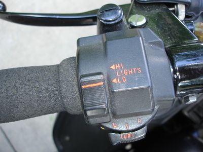
The high beam switch is also a simple switch and generally causes few problems. I don't remember a post on a bad high beam switch in the last 5 years on the forum. A major reason is probably due to the switch is one of the least used, and therefore doesn't have the associated wear that some other switched do. A interesting note on this switch is that from the wiring diagrams I checked, both the low and high beam are on together when the bike is started.
Clutch Switch:
The clutch switch's purpose is to allow the bike to be started in gear when you pull in the clutch lever. It is non-repairable to my knowledge and must be replaced if bad. It is cylindrical in shape and held in a recess by a set screw under the clutch lever. Testing is straight forward by removing the switch and the connectors and testing for continuity while operating the plunger. It can also be tested without removal, and the terminals exposed by removing the wire connectors.
Brake Switches:
There are two switches associated with allowing the rear brake light to operate when the brakes are applied. The switch under brake lever at the handlebars is a standard microswitch design. To my knowledge, it is also unrepairable, or not cost effective to do so as these switches are available from multiple sources for little money. Testing is similar to the clutch switch, with checking continuity as the switch is actuated. The switch can be removed if necessary by removing a screw holding the switch to the bracket. There is also a locating pin that the switch must be gently pried off to completely remove.
The rear brake switch is located on the frame close to the rear wheel. It is cylindrical in shape and has a plunger extending from the bottom end. To a hole in this plunger, a long spring is attached to the brake pedal arm. Pressing down on the brake pedal pulls on the spring and the plunger and makes a contact inside the switch. These have a adjusting nut on the switch body to allow for adjustment for brake pedal travel. I would adjust so that a slight, but definite, depression of the brake pedal illuminates the brake light. Since this plunger lives in a harsh environment, occasional cleaning and lubing of the plunger will forestall most problems with this switch.
Ignition Switch:
The ignition switch performs several functions and therefore is a bit more complex than some other switches. It's main function is to allow current to flow thru the electrical system when the key is turned. Different bikes have different positions for the key to turn to, but I believe all have: Lock, Off, On, and Park. When turned to the lock position, and the key is pushed in, a rod is extended from the switch mechanism into a slot on the handlebar stop. Then withdrawing the key effectively locks the front wheel in a right turning position. The Off and On are self explanatory. The park position turns on a small lamp in the tail light to warn others that a bike is there. In the U.S. it probably is little or never used.
This switch suffers some issues due to age and use. The main one seems to be a loss of electrical contact when the key is turned to on. This is resolved by removing the switch from the bike and cleaning out the contact area. First, use a long extension to access the two 10mm bolts that hold the switch assembly to the triple tree. Sometimes it is easier to first unplug the electrical connector, sometimes you can do that when the switch is loose. With the switch on a bench on a clean towel, turn the key until the white tabs can be pushed in to release the barrel. On a 650, this is the Accessory position, I'm not sure on the CX's. With the tabs retracted, slip the lower contact assembly from the upper key part. You should now have access to the actual contacts after removing a plastic disk from the assembly.
The contacts are "U" shaped bits of copper, pushed outward by small springs. (Now you know the reason for the clean towel) They are generally gummy and may have worn to the extent that they no long can easily be retracted into their slots. I had one several months ago that I had to carefully pare the plastic to allow for the "U" contacts to work. When everything is clean, apply some dielectric grease to the contacts and reassemble. The complete job is actually less daunting than it appears here. Just take your time and remove parts carefully and slowly.
Here is more information on removing and cleaning the ignition switch: Cleaning the Ignition Switch
Starting Solenoid:
The solenoid is technically a switch, even tho there is no mechanism on the solenoid to manually switch it. It is basically a electromagnet that pulls a plunger into contact with two other contacts. It's purpose is to transfer about 100 amp to the starting motor for engine starting. A regular switch such as the horn switch may be able of transferring 3-4 amps. A large load such as the starting motor would immediately burn a switch like that out. There are several issues that do develop with the solenoid that can be addressed.
The indications that something is wrong with the solenoid are when the bike doesn't crank with a known good battery. If you only hear a "Click" when the button is pushed, likely the solenoid is not making good internal contact from the battery cable to the starting motor cable. If there is not even a "Click", it is possible that the magnet wires have been broken. (This would be a rarity, more likely that the solenoid is not receiving 12 volts to the plunger coil). A simple test of the starting system is to bridge the two large terminals on top of the solenoid. Do this with a old screwdriver or other substantial metal object. Do not use a light guage wire as they cannot carry the starting motor current and will immediately melt. Hold the screwdriver on one terminal and then bridge to the other terminal in a deliberate manner. There will likely be a few sparks, but by not being shy about the procedure, you should be fine. This essentially bypasses the solenoid, so if the engine cranks, the starting motor is OK. There is still the starter button circuit that could still be bad tho.
The CX models are easier to open up and clean, I have not tried doing it on a GL. The general idea is to remove the two Philips screws that hold the case together and VERY gently guide the two small wires thru the top cap. This can involve some head scratching, as these wires go to the electromagnet and become very thin inside the lower case and easily broken. Once thru, the top cap can be removed and the plunger drawn out. The two large terminals on the cap can also be removed by loosening the large bottom nuts. When these are off, the contacts will come out of the lower shell. They can then be cleaned, or reversed. Simply move them to the opposide side.
The plunger contacts can also be wire brushed, sanded, and on some models turned upside down to present a new contact area for the posts. I have successfully repaired 3-4 of these, but replacement may be a better option. On the CX models, any simple solenoid from a lawn tractor, ATV, or most motorcycles will provide the function needed. The GL models would require a slightly modified wiring as they combine the bikes main fuse in the same unit with the solenoid.
Here is a post from Wolfgang on repairing the solenoid:
The CX starter relay (solenoid) is much easier to repair.
http://cx500forum.com/forum/attachments/technical-help-forum/13334d1405624471-replacement-solenoid-startrelais-mit-kabeln.jpg%7Cthumb%7CName: Startrelais-mit-kabeln.jpg
That's it ;-)
| This image has been resized. Click this bar to view the full image. The original image is sized 550x609. |
http://cx500forum.com/forum/attachments/technical-help-forum/13335d1405624557-replacement-solenoid-isolierung-und-halter-wegbi.jpg%7Cthumb%7C541x600px%7CName: Isolierung-und-Halter-wegbi.jpg
Unscrew the two 10mm nuts for the plus wires. Unscrew the two phillips drive screws. Nr. 1: Push the black isolation tube into the direction of the white plug: For that: Take the black plastic cap into your left hand. With the right hand) push lightly the two wires into the cap.
- !!! Don't try to tear only on the black cap, this can tear the wires from their soldering points.!!!
) For the lefty's (left handed persons) change the term "right" to the other right (left) ;-))
BTW: I don't see any sealant for the wires going through the black cap.
Nr. 2: Bend the metal holder for the wires a bit beside.
If You have done this You'll see the big copper contacts. Often they are so black corroded/burnt that not enough current can run to start the starter motor.
http://cx500forum.com/forum/attachments/technical-help-forum/13336d1405625366-replacement-solenoid-kupferkontakte.jpg%7Cthumb%7CName: Kupferkontakte.jpg
Remove the two single copper contacts from the black cap. (unscrew the two nuts backside ) Clean these copper contacts with a point file, Dremeling, glass fiber eraser, .....etc.. You want the surface to remain flat and square to the other contact. Even a quick polish would be good. Sandpaper embeds grit into the surface and is not recommended. No dirt shold come around the big flat copper contact of the coil. This contact plate is fixed with a rod and a spring. Check it for a free mowing.
Before all that work: Check the resistance if the coil. On the white plug my values are ~ 4.5 Ohms.
Then reassemble and re-install the relay to the bike.
I'm rather sure now the starter will have more power than the engine.  To make this "repair" more than excellent You will not need more than 45 minutes.
So You can save another 25$ for a unknown used solenoid.
Have fun ;-))
Gruesse
WolFgang
Note: the internal contacts can also be removed and flipped over to present a new contact face. This may be a better way than sanding a dish shape to the contact bar. (Blue Fox)
Restoring the switch's appearance:
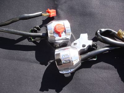
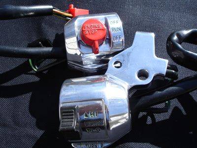
OK, I first need to plead OCD when it comes to restoring bikes. That being said, if you want to improve the appearance of the switches, here is how I have done it. The switches (in most cases) are aluminum that has been anodized to a almost black color. If this wears off, or starts to look shabby, the only reasonable remedy is to repaint with the highest quality paint you can find. I think semi-gloss black is the closest to the original look. A rattle can is the logical way to paint, unless you have some semi-gloss automotive two stage paint already and a air brush to apply.
I have removed the anodize by using oven cleaner and other chemicals to remove the anodize. Then polished the controls on a buffing wheel. The polishing is difficult to do perfectly as there are many nooks and cranny's in the control clamshells. The ones I did came out OK, and I sold them on the bay for I believe around $40.
If you do decide to paint, remember to throughly clean the parts and wipe down with lacquer thinner before applying several thin coats of paint. After the paint is dry, you now have all the lettering painted as well as the other areas. If the lettering was sharp and in good condition, a Q-Tip dipped in lacquer thinner and lightly brushed over just the raised letters will remove the black paint. The longer you wait to do this, the harder the paint will be to remove. I have also used a cleaner stick for a VCR that had a chamois tip that was flat and hard, to spirit the paint off the letters.
If the original paint was worn or missing, you must now repaint the lettering. Quite a challenge with most household brushes. I purchased a good artist brush with a very. very fine tip to layer paint on the letters. Fiddly at best, and a disaster most of the time. I used Day-Glow orange and for some models a medium green for the paint. After a few experiments, I came across a technique of using a section of rubber fuel hose.
Flex the hose slightly so that the flat area of the hose matches the length or is slightly less than the lettering you want to paint. Apply a layer of paint to a cardboard square and lightly pass the hose thru this paint. You only want a very light coating on the hose. Then before things start to dry, gently touch the hose with the paint to the lettering you want to restore. The paint will be transfered to only the raised letters, and if done correctly with the proper amount of paint on the hose, you won't transfer enough to paint between the letters. Practice is the key here, but the system seems to work well.
by Blue Fox
More on switches here; Rebuilding handlebar switches


This site is backed by Number 85, who provide the hosting. If you need a website done, get in touch with them.
